Power switch device

a power switch and switch technology, applied in the direction of manufacturing tools, transportation and packaging, emergency power supply arrangements, etc., can solve the problems of large circuit size, severe power consumption, and important power management, and achieve the effect of small circuit layout and low power consumption

Inactive Publication Date: 2008-08-19
HIMAX TECH LTD
View PDF5 Cites 70 Cited by
  • Summary
  • Abstract
  • Description
  • Claims
  • Application Information

AI Technical Summary

Benefits of technology

[0009]Another aspect of the invention is to provide a power switch device for supplying a power source taking in high and low input voltages and the power switch may have compact circuit size and low power consumption.
[0012]In the invention, the power switch device is manufactured by low voltage manufacturing process. Therefore, the power switch device has small circuit layout and low power consumption.

Problems solved by technology

With the high demand on portable electronic devices, power management is an important issue for maintaining operation time.
However, if the power source Vpp1 is used in a high voltage application, the power switch device has to be manufactured by high voltage manufacturing process.
But the resultant power switch device by high voltage manufacturing process has large circuit size and severe power consumption.

Method used


Image

  • Power switch device
  • Power switch device
  • Power switch device

Examples


Embodiment Construction

[0020]Reference will now be made in detail to the present preferred embodiments of the invention, examples of which are illustrated in the accompanying drawings. Wherever possible, the same reference numbers are used in the drawings and the description to refer to the same or like parts.

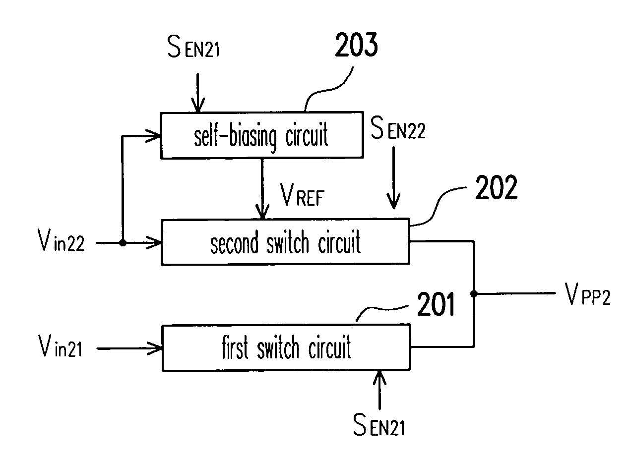
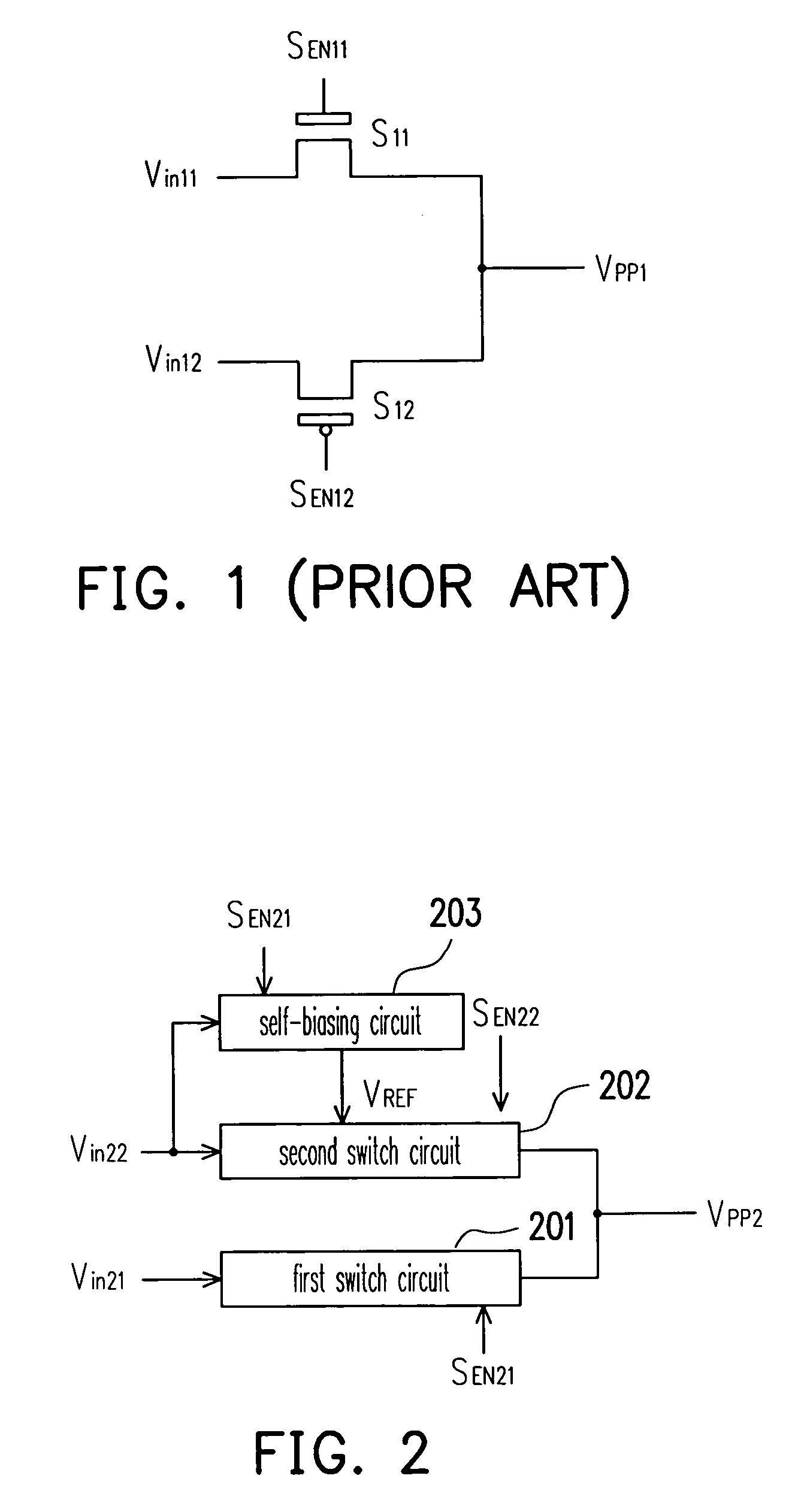
[0021]FIG. 2 shows a power switch device according to an embodiment of the present invention. As shown in FIG. 2, the power switch device includes a first switch circuit 201, a second switch circuit 202 and a self-biasing circuit 203. The first switch circuit 201 and the second switch circuit 202 respectively receive input voltages Vin21 and Vin22. Output terminals of the first switch circuit 201 and the second switch circuit 202 are coupled to each other. The self-biasing circuit 203 is coupled to the second switch circuit 202 for supplying a reference voltage VREF to the second switch circuit 202. An enable signal SEN21 is used for controlling the first switch circuit 201 and the self-biasing circu...


PUM

PropertyMeasurementUnit
voltageaaaaaaaaaa
output voltage Vpp2aaaaaaaaaa
voltageaaaaaaaaaa

Abstract

A power switching device which is used to receive plenty of input voltage and output a switch voltage is provided. The device comprises a first switching unit, a second switching unit, and a self-bias unit. The power switching device outputs a switch voltage according to the outputs of the first switching unit and the second switching unit. The self-bias unit outputs a reference voltage to the second switching unit. The first switching unit outputs a first input voltage as the switch voltage according to a first enable signal. The second switching unit outputs a second input voltage as the switch voltage according to the reference voltage and a second enable signal.

Description

CROSS-REFERENCE TO RELATED APPLICATION[0001]This application claims the priority benefit of Taiwan application serial no. 95106967, filed on Mar. 2, 2006. All disclosure of the Taiwan application is incorporated herein by reference.BACKGROUND OF THE INVENTION[0002]1. Field of Invention[0003]The present invention relates to a power switch device. More particularly, the present invention relates to a power switch device with a self-biasing circuit.[0004]2. Description of Related Art[0005]With the high demand on portable electronic devices, power management is an important issue for maintaining operation time. Generally, the portable electronic device integrates a lot of components and those components may be powered by different power sources.[0006]FIG. 1 shows a conventional power switch device including switches S11 and S12. First terminals of the switches S11 and S12 receive input voltages Vin11 and Vin12 respectively. Second terminals of the switches S11 and S12 are coupled togeth...

Claims


Application Information

Patent Timeline
Patent Type & Authority Patents(United States)
IPC IPC(8): H02J1/00H02J1/10H02J3/00
CPCH02J1/10
Inventor CHEN, TIAN-HAU
Owner HIMAX TECH LTD
Why Eureka
Try Eureka