Harsh environment coil-actuator for a cartridge type valve

a cartridge type, coil-actuator technology, applied in the direction of valve operating means/release devices, magnets, magnetic bodies, etc., can solve the problems of difficult environmental disposal and rapid decomposition of plating, and achieve the effect of improving the efficiency of coil actuators, increasing the flux path and efficiency of coils, and facilitating the closure of coil actuators

Active Publication Date: 2008-08-19
DELTA POWER
View PDF6 Cites 25 Cited by
  • Summary
  • Abstract
  • Description
  • Claims
  • Application Information

AI Technical Summary

Benefits of technology

[0011]Another object of the present invention is to provide a harsh environment coil-actuator structure or assembly with an increased efficiency “magnetic flux” (afterwards referred to as “flux”) carrying capability actuator to increase the force generated by coil energization between the coil and the armature connected to the valve spool.
[0013]Yet another object of the present invention is to reduce or eliminate external or exposed metal parts of the coil actuator which are conventionally plated Hexavalent Chromium (Hexachrome) conversions used typically on Zinc Plating on many commercial fasteners and on most products in the hydraulic cartridge valve industry. It is notable that this plating degrades rapidly under adverse conditions and is difficult to dispose of environmentally.
[0015]In one of the embodiments shown, the disc is also engaged in its interior apertured periphery by a sleeve which axially projects beyond the plane of the Disc, The sleeve forms, in conjunction with the disc, a lip or interior wall for inhibiting radially inward displacement of the O-ring. Preferably, a second radially spaced apart second wall or lip is formed by a terminal portion of the plastic over mould or cover, forming an annular receptacle for receiving the O-ring. The O-ring is in sealing contact with a capture element (e.g. a nut) displaceably mounted on the projecting extended end of a (internal) plug which is part of an insertable cartridge in which the valve spool may reciprocate in response to coil energization. The capture element or nut also preferably engages at least the terminal portion of the plastic over mould and the O-ring and thus environmentally seals the coil. When the capture nut is assembled on to the plug, in sealing engagement with the O-ring, it simultaneously engages the axially extending lip or axially extending sleeve. Inasmuch as the sleeve engages the flux connectors or discs, which is in engagement with or forms part of the internal frame, an increased efficiency flux path is created.
[0016]To facilitate closure of the coil actuator and assembly of the same, while simultaneously increasing the flux path and efficiency of the coil when in operation, a retainer, in the illustrated instance a nut similar to the capture element or nut is preferably connected adjacent to the remote or distal end of the cartridge so that as the capture element is engaged with the opposite end of the plug, the nut effects sealing of the remote end of the coil actuator. Simultaneously, therefore, metal to metal engagement with the sleeve occurs through the second flux path connector or washer like disc which lies intermediate the nut and the sleeve portion of the frame.
[0017]As shown in the drawings and as described hereinafter, the receptacle for capturing the O-ring may be formed in a number of ways. The system requirements being (1) that the capture nut is in a flux path with the disc and frame of the coil actuator assembly to optimize the flux path and increase efficiency of the coil actuator, and; (2) that the O-ring in conjunction with the encapsulation, and the capture nut inhibits contaminant entry into the assembly. To provide additional environmental sealing of the coil-actuator, the coil lead wire termination includes cold forming or latched caps over lead wires to thereby provide environmental (or dunk) sealing of the external wire leads.
[0018]Using coils with external O-rings and separate flux path connectors or metal end washer like discs, which are all retained in the coil-actuator assembly, and mated in assembly with a cartridge valve insert by a capture element or nut, constructs a one-piece, but separate part replaceable, coil-actuator assembly. This construction has the advantage of efficiently closing the magnetic path even though it is not a one-piece assembly.

Problems solved by technology

It is notable that this plating degrades rapidly under adverse conditions and is difficult to dispose of environmentally.

Method used


Image

  • Harsh environment coil-actuator for a cartridge type valve
  • Harsh environment coil-actuator for a cartridge type valve
  • Harsh environment coil-actuator for a cartridge type valve

Examples


Embodiment Construction

[0029]While the present invention is susceptible of being made in any of several different forms, the drawings show a particularly preferred form of the invention. One should understand, however, that this is just one of many structures that exemplify the construction of and manner in which the invention can be made. In the drawings, like reference numerals refer to like parts throughout the several views.

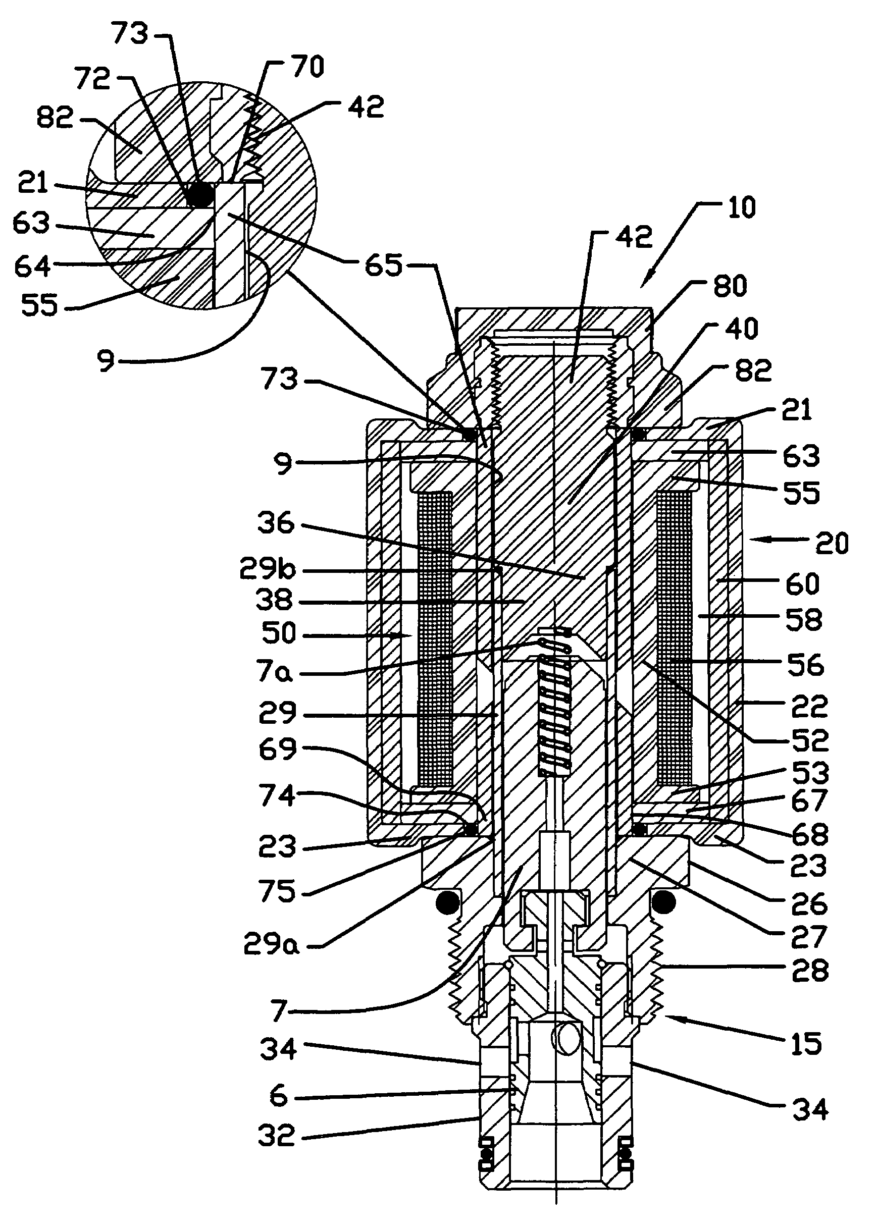
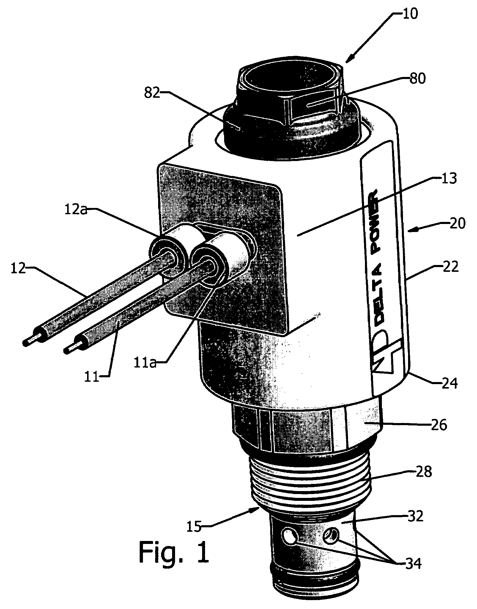
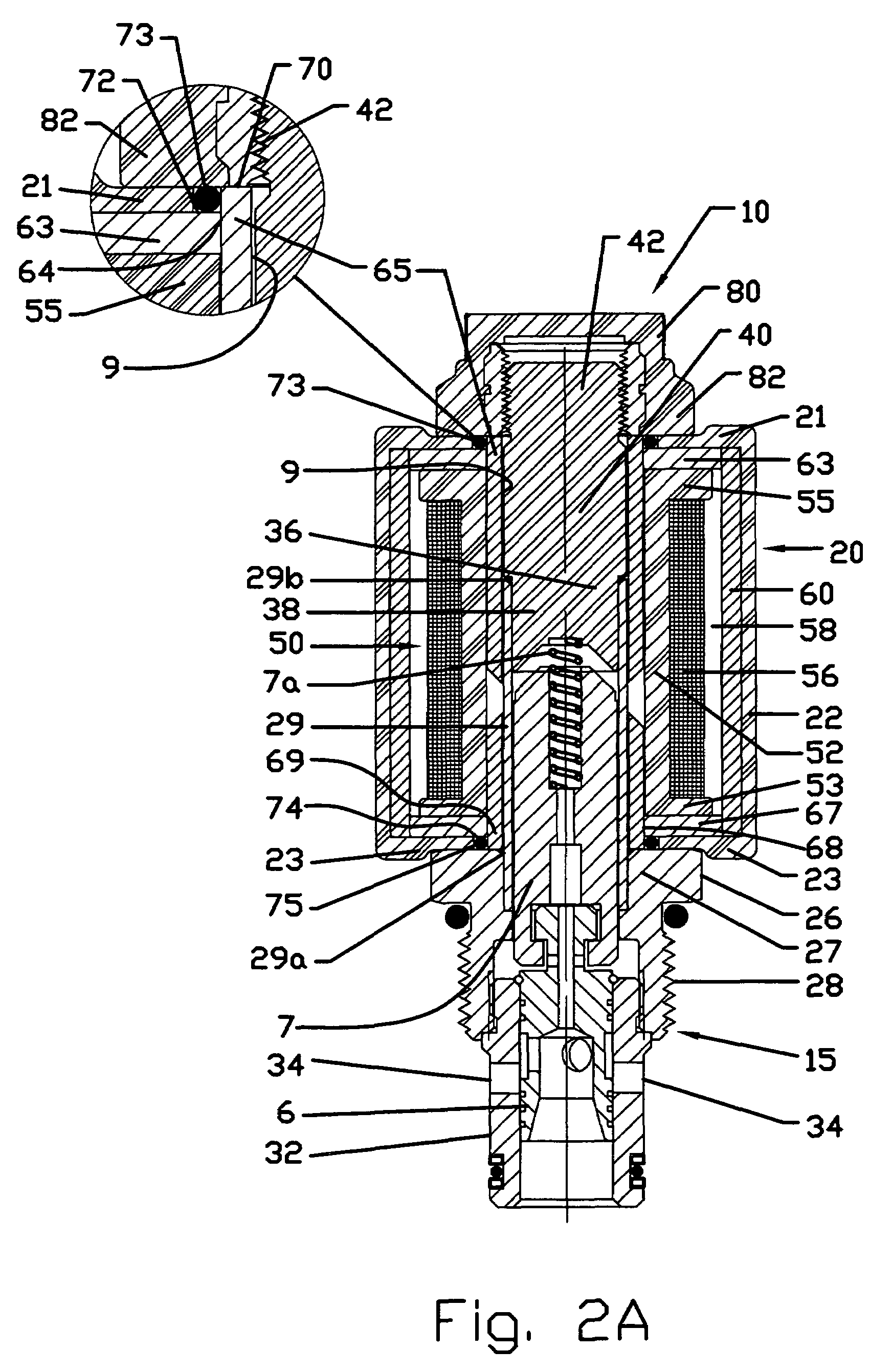
[0030]Turning now to the drawings, FIG. 1 illustrates a solenoid operated cartridge valve 10, comprising a coil-actuator assembly 20 and a cartridge 15, the cartridge being dimensioned for insertion within a bore 9 coaxial with the axis of a coil carrying bobbin 52 (FIGS. 2A-2F). The valve 10 is adapted, as discussed hereinafter, to be inserted and secured into a valve bonnet or hydraulic manifold (not shown). The valve is operated by applying a source of electrical power to external leads 11, 12 which extend into the novel coil-actuator 20 of the present invention and are coupled ...


PUM

PropertyMeasurementUnit
magnetic fluxaaaaaaaaaa
diameteraaaaaaaaaa
flux densityaaaaaaaaaa

Abstract

Illustrated is a cartridge type solenoid valve with a coil-actuator structure which employs O-ring seals to inhibit harsh environment entry into the coil-actuator and allows for metal to metal contact with the frame to increase the flux density and path for flux when the valve is in operation. A plastic over mould is encapsulated over the metal frame (in one embodiment a sleeve) which is shaped to provide efficient magnetic flux carrying capability, as well as abut a flux connector, e.g. a disc adapted to capture an O-ring. The O-ring is in sealing contact with a capture element, e.g. a nut on the projecting extended end of an insertable cartridge having an internal plug, environmentally sealing the coil. When the capture nut is assembled on to the plug, in sealing engagement with the O-ring and simultaneously engaging the plug, an increased efficiency flux path is created. The lead wire termination version includes cold forming or latched caps over lead wires to provide environmental (or dunk) sealing.

Description

CROSS-REFERENCE TO RELATED PATENT APPLICATIONS[0001]Applicants hereby claim the benefit under Title 35, United States Code § 119(e) of U.S. provisional application 60 / 652,721, filed on Feb. 14, 2005.BACKGROUND OF THE INVENTION[0002]1. Field of the Invention[0003]The present invention relates to solenoid valves and more particularly relates to an improved construction for coil-actuators for cartridge type solenoid valves which may be subject to severe environmental conditions.[0004]2. Background[0005]For many years the mobile hydraulics industry has been looking for an economical but durable coil used on their valves even when the valves are exposed to harsh environments. For this reason expensive, external frame (“Shell-over”), non-recyclable “Epoxy based Thermoset” coils have been utilized and are still employed for most severe, environmentally unfriendly, applications. However for economic reasons, where the most severe environmental conditions do not exist, less expensive, recycl...

Claims


Application Information

Patent Timeline
Patent Type & Authority Patents(United States)
IPC IPC(8): F16K31/02H01F7/08
CPCF16K31/0668F16K3/26
Inventor TACKES, JOHN N.AMLADI, DILIP M.
Owner DELTA POWER
Why Eureka
Try Eureka