Cylindrical roller bearing

a technology of cylindrical roller bearing and roller bearing, which is applied in the direction of rolling contact bearings, shafts and bearings, rotary bearings, etc., can solve the problems of ineffective techniques, problems such as the stability of quality, and the bearing is broken, so as to improve seizure resistance and seizure resistance, and improve the allowable rotation speed. , the effect of improving seizure resistan

Active Publication Date: 2008-08-26
NSK LTD
View PDF19 Cites 22 Cited by
  • Summary
  • Abstract
  • Description
  • Claims
  • Application Information

AI Technical Summary

Benefits of technology

[0021]According to the cylindrical roller bearing described in (1), since the end face of the roller contacting with the roller guide-surface of the flange portion is configured in the aforesaid manner, a contact surface pressure at the contact portion between the roller guide-surface of the flange portion and the end face of the roller at the time of loading an axial load on the cylindrical roller bearing can be made small. As a result, a PV value (a product of the contact surface pressure P and a slip velocity V) of the contact portion can be reduced and the seizure resistance can be improved. Thus, according to the aforesaid configuration, the seizure resistance can be improved and an allowable rotation speed can also be improved without increasing the size of the bearing.
[0023]Further, according to the cylindrical roller bearing described in (3), the radial direction distance at the cross point based on the configuration of the end face of the roller and the configuration of the roller guide-surface of the flange portion are set in the aforesaid range. Thus, even when an axial load of a predetermined value or more is loaded on the cylindrical roller bearing and so the contact portion shifts towards the peripheral surface of the flange portion due to the influence of the tilt, the contact portion is prevented from protruding from the roller guide-surface. Further, the contact surface pressure at the contact portion between the roller guide-surface of the flange portion and the end face of the roller can be made small. As a result, the PV value (a product of the contact surface pressure P and a slip velocity V) of the contact portion can be reduced and the seizure resistance can be improved. Thus, according to the aforesaid configuration, the seizure resistance can be improved and the allowable rotation speed can also be improved without increasing the size of the bearing.

Problems solved by technology

When the friction becomes remarkable due to the high speed rotation, wear and seizure are caused and so there may arise a case that the bearing is broken in an early stage.
However, the improvement of the surface roughness and the provision of the working grain as respectively disclosed in the JP-A-7-42746 and JP-A-7-91452 cause a problem of the cost-up and a problem in the stability of quality due to the particular processing equipment and the extension of the processing time.
On the other hand, even in the case where the roller and the flange portion are changed in the particular shapes as disclosed in JP-A-6-241235 and JP-A-9-236131, respectively, these techniques are not effective since the processing of the roller and the additional processing of the inner and outer rings raise the costs thereof.
Thus, there arises a problem that the contact ellipse may protrude from the relief groove of the inner ring flange surfaced or the outer diameter of the flange surface depending on an amount of the axial load, so that an edge load is generated at the boundary surface between the contact ellipse and the relief groove or the boundary surface between the contact ellipse and the outer diameter portion of the flange portion.
However, in this case, since the slippery degree between the roller and the flange portion becomes large, a heat value increases, whereby there arises such problems that the temperature of the bearing increases, scoring or seizure etc. of the flange portion occurs.

Method used


Image

  • Cylindrical roller bearing
  • Cylindrical roller bearing
  • Cylindrical roller bearing

Examples


first embodiment

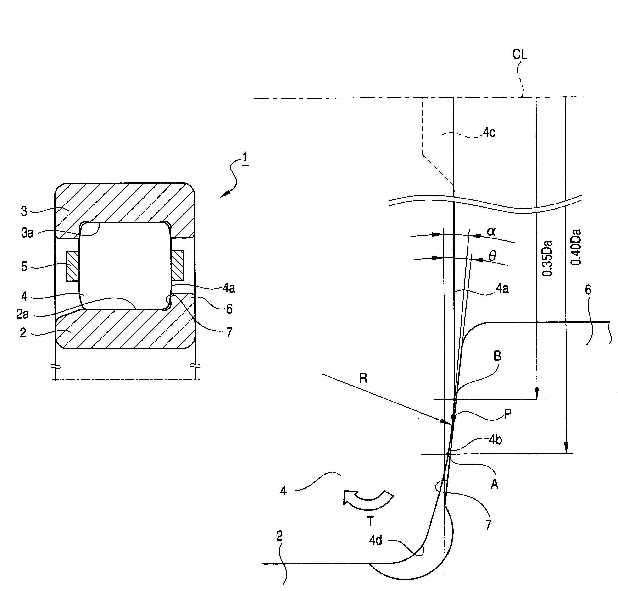
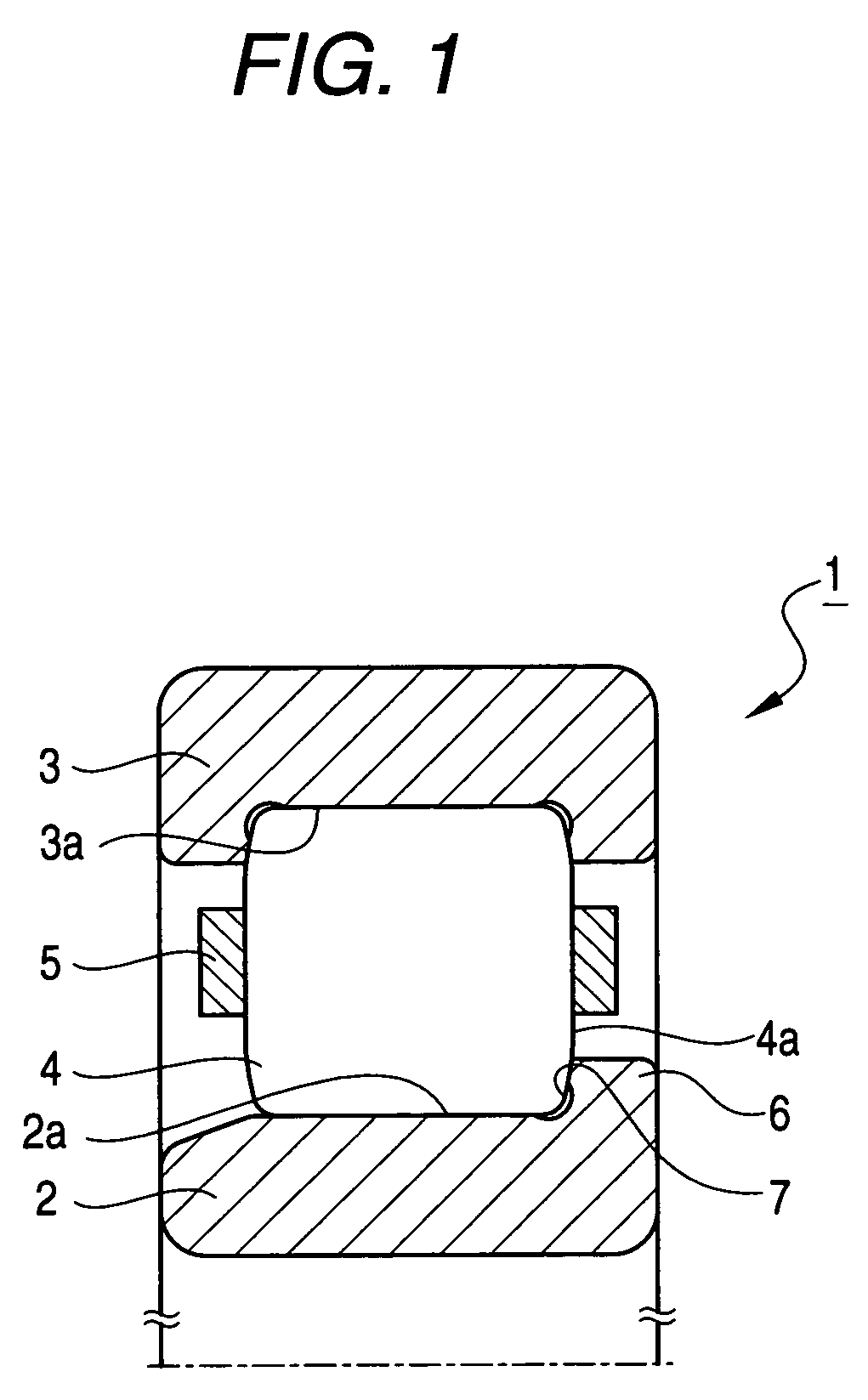
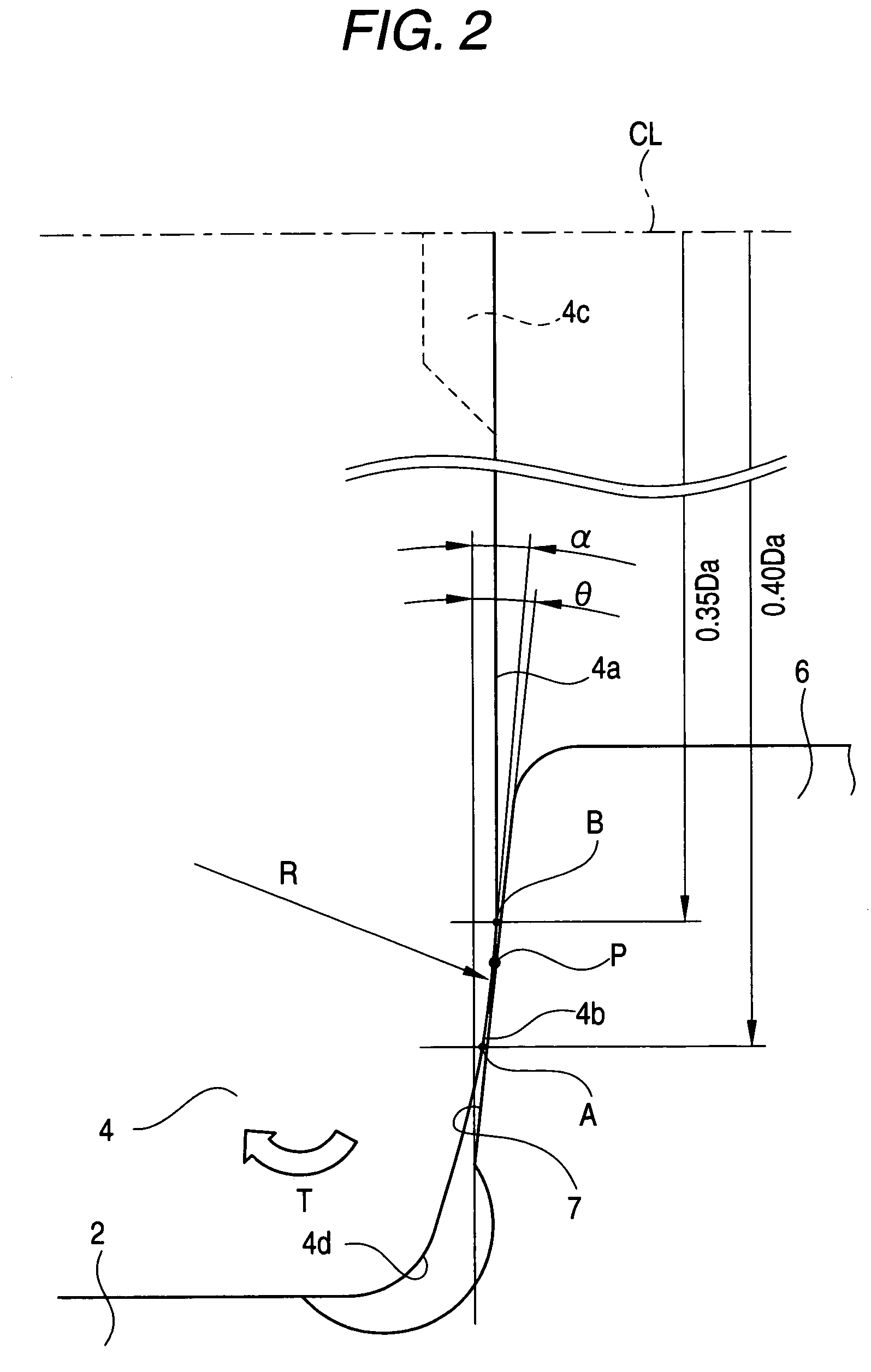
[0035]First, the cylindrical roller bearing according to the first embodiment of the invention will be explained. FIG. 1 is a sectional diagram showing a part of the cylindrical roller bearing according to the first embodiment. FIG. 2 is an enlarged diagram of a main part showing a portion where the roller guide-surface of a flange portion contacts with the end face of the cylindrical roller.

[0036]As shown in FIG. 1, the cylindrical roller bearing 1 includes an inner ring 2, an outer ring 3, cylindrical rollers 4 and a retainer 5. The inner ring 2 includes an inner ring raceway surface 2a at the center portion of the outer peripheral surface thereof. The outer ring 3 includes an outer ring raceway surface 3a at the center portion of the inner peripheral surface thereof. The cylindrical rollers 4 held with a predetermined interval along the circumferential direction by the retainer 5 are disposed so as to rotate freely between the inner ring raceway surface 2a and the outer ring race...

second embodiment

[0062]Next, the cylindrical roller bearing according to the second embodiment of the invention will be explained. FIG. 6 is a sectional diagram showing a part of the cylindrical roller bearing according to this embodiment. FIG. 7 is an enlarged diagram of a main part showing the roller guide-surface of the flange portion and the end face of the cylindrical roller in a state where no load is acting in the cylindrical roller bearing of FIG. 6. FIG. 8 is an enlarged diagram of a main part showing the roller guide-surface of the flange portion and the end face of the cylindrical roller in a state where a load is acting in the cylindrical roller bearing of FIG. 6.

[0063]The cylindrical roller bearing shown in FIG. 6 is a cylindrical roller bearing for a manual transmission for a truck to which a large axial load together with a radial load is applied. The cylindrical roller bearing 21 includes an inner ring 22, an outer ring 23 and cylindrical rollers 24. The inner ring 22 includes, at th...


PUM


Abstract

A cylindrical roller bearing includes an inner ring having a flange portion provided with a roller guide-surface which guides the end faces 4a of the cylindrical rollers having diameter of Da. The end face 4a away from a center axis of the cylindrical roller by 0.40 Da in the radial direction is a first position A, and the end face 4a away from the center axis by 0.35 Da is a second position B, the end face 4a contacts with the roller guide-surface between the first and second positions A and B, the end face 4a has a convex-shaped crowning portion 4b having a continuous curve which passes the first and second positions A and B, and an angle α formed between a line connecting the first and second positions A and B and a line perpendicular to the center axis is set to be 0.5° or less.

Description

TECHNICAL FIELD[0001]The present invention relates to a cylindrical roller bearing which is used for the transmission etc. of an automobile and durable of an excessive axial load applied thereto, and in particular relates to the improvement of a cylindrical roller bearing which seizure resistance is improved so as not to cause the seizure immediately even in a case of a high-speed rotation or a case of using low-viscosity oil or a case where a lubricating oil device is failed and lubricating oil can not be supplied sufficiently.BACKGROUND ART[0002]In general, a cylindrical roller bearing is configured in a manner that, in order to guide cylindrical rollers in the circumferential direction of a raceway ring, a flange portion is provided at the end portion of the raceway ring, and the end face of each of the rollers is made in slide contact with a roller guide-surface formed at the inner surface of the flange portion. A cylindrical roller bearing used for the transmission etc. of an a...

Claims


Application Information

Patent Timeline
Patent Type & Authority Patents(United States)
IPC IPC(8): F16C33/58F16C19/00F16C19/26F16C33/34
CPCF16C19/225F16C19/26F16C33/34F16C33/585F16C33/605F16C2240/40F16C2240/50
Inventor TAKEMURA, HIROMICHISATO, MASANAO
Owner NSK LTD
Why Eureka
Try Eureka