Card adapter

a card adapter and card technology, applied in the direction of electrical discharge lamps, coupling device connections, instruments, etc., can solve the problems of not being able to accept a new type of memory card with two arrays of electrodes, electronic devices cannot accept different standard memory cards, etc., and achieve the effect of simple appearan

Inactive Publication Date: 2008-08-26
HOSIDEN CORP
View PDF5 Cites 41 Cited by
  • Summary
  • Abstract
  • Description
  • Claims
  • Application Information

AI Technical Summary

Benefits of technology

[0011]The card adapter of the present structure consists of two groups, the first contact member and the second contact member in contrast to the conventional structure with only one group of contact member. The first and second contact member are disposed within the main body in such a way that the first contact points of the first contact member and the second contact points of the second contact member are located at different positions in a direction to which a memory card is inserted. Therefore, when using the memory card inserted into the card adapter of the present structure, even the memory card having two arrays of electrodes can reliably contact electronic devices comprising no connectors supporting the memory card.
[0012]As mentioned above, the card adapter of the present structure enables the use of memory cards having two arrays of electrodes. It also allows the memory cards to be made smaller. The versatility of electronic devices is also improved.
[0014]In the card adapter of the present structure, as the base portions of the first contact member and the base portions of the second contact member are located at different positions in a direction of thickness of the main body, the first contact points of the first contact member and the second contact points of the second contact member can be located at different predetermined positions respectively while the first contact member and the second contact member can be insulated from each other. In addition the base portions of the first and second contact member do not exist in a common flat surface; therefore, the two dimensional spread of two contact member can be reduced as well as the occupied area of the main body. The base portions of the first contact member and the base portions of the second contact member partially overlap as they are located at different positions in a direction of thickness. The base portions of the first and second contact member are much thinner than the main body; therefore, the thickness of the card adapter does not increase.
[0016]In the card adapter in accordance with the present structure, the first and second contact members are embedded into the first and second insulators by insertion molding; therefore, the first and second contact members are insulated more reliably. Since the first insulator in which the first contact member is embedded and the second insulator in which the second contact member is embedded are integrated, the rigidity (strength) of the contact member increases and the durability of the card adapter is improved. The toughness of the card adapter is also improved as the distortion of the insulators is reduced compared to the insulators that are not integrated. As the integration allows the first and second insulators to be treated as one part, insulator testing, such as conduction and compression testing can be conducted at once. This enables the efficiency in manufacturing card adapters to be improved.
[0018]In the card adapter of the present structure, the first and second insulators can be easily assembled as they can be integrated simply by fitting the convex portion formed in the second insulator into the hole portion formed in the first insulator. With the insulators integrated, the first connecting portions of the first contact member and the second connecting portions of the second contact member lie in a common flat surface; therefore, the card adapter with the memory card inserted can be connected into a connector of an electronic device smoothly and reliably.
[0020]In the card adapter of the present structure, there is no floating ground member as the metal case of the main body functions as a ground member of the memory card. This results in a more compact, thinner and lightweight card adapter as well as a card adapter with a simple appearance. By providing the main body with the metal case, the memory card is electromagnetically shielded from an electronic device which is on the outside of the card adapter. This prevents electromagnetic waves from leaking from the memory card. The memory card is less affected by external electromagnetic waves as the metal case shields external electromagnetic waves.

Problems solved by technology

However, an electronic device can only accept a memory card complying with a particular standard, for example, a memory card compatible with the connector of the electronic device.
Therefore, an electronic device may not accept different standard memory cards as they are.
Therefore, the new type of memory card having two arrays of electrodes can not be used in a card adapter with one array of contact member disposed in a width direction within its main body, such as that described in the patent document.
Then, if a user-owned electronic device doses not comprise any connectors supporting a memory card having two arrays of electrodes, the user can not use the memory card having two arrays of electrodes.

Method used


Image

  • Card adapter
  • Card adapter
  • Card adapter

Examples


Embodiment Construction

[0032]An embodiment of the present invention is described hereinafter with reference to the figures. The invention is not limited to the following embodiment and constructions described in the figures, and include equivalents thereof.

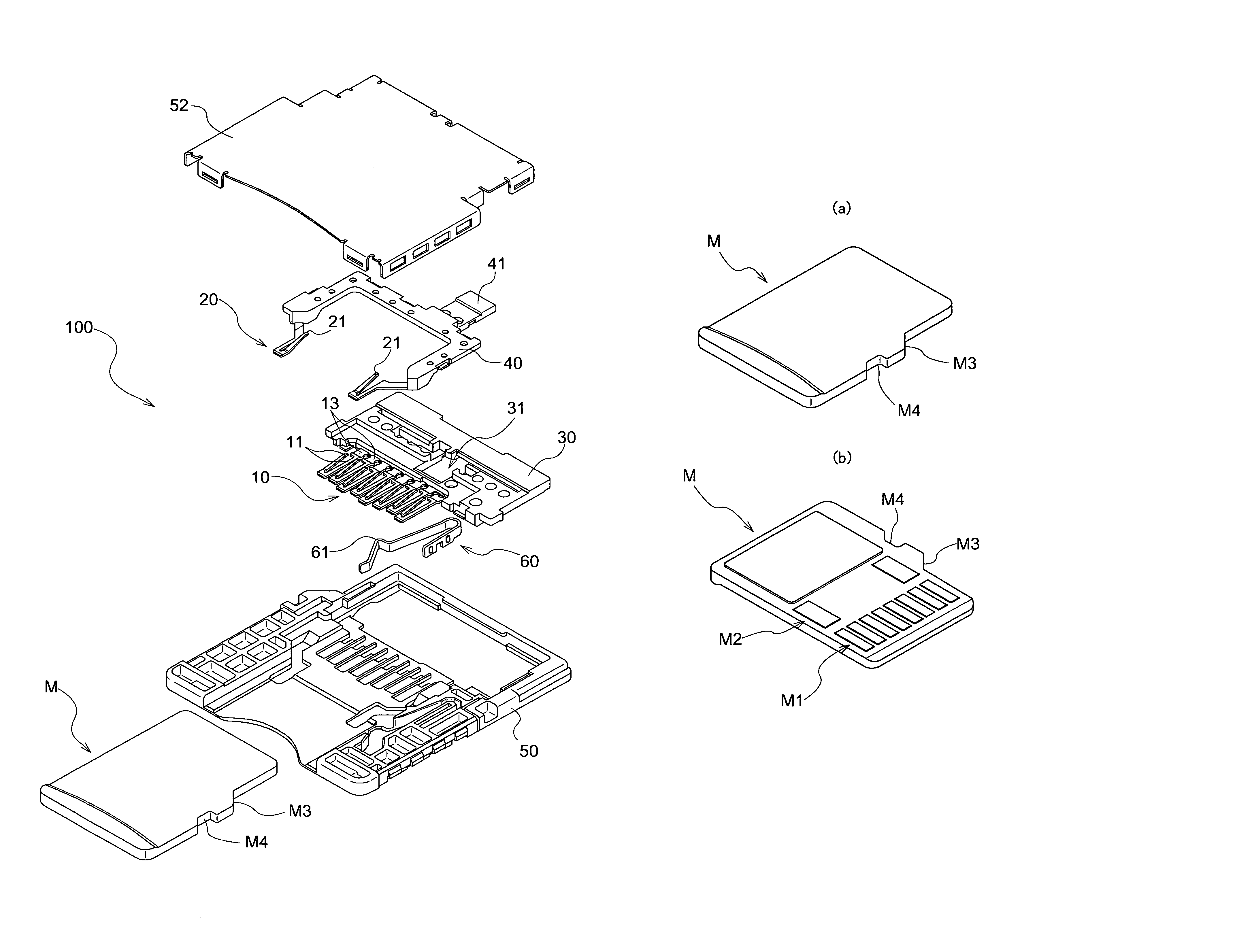
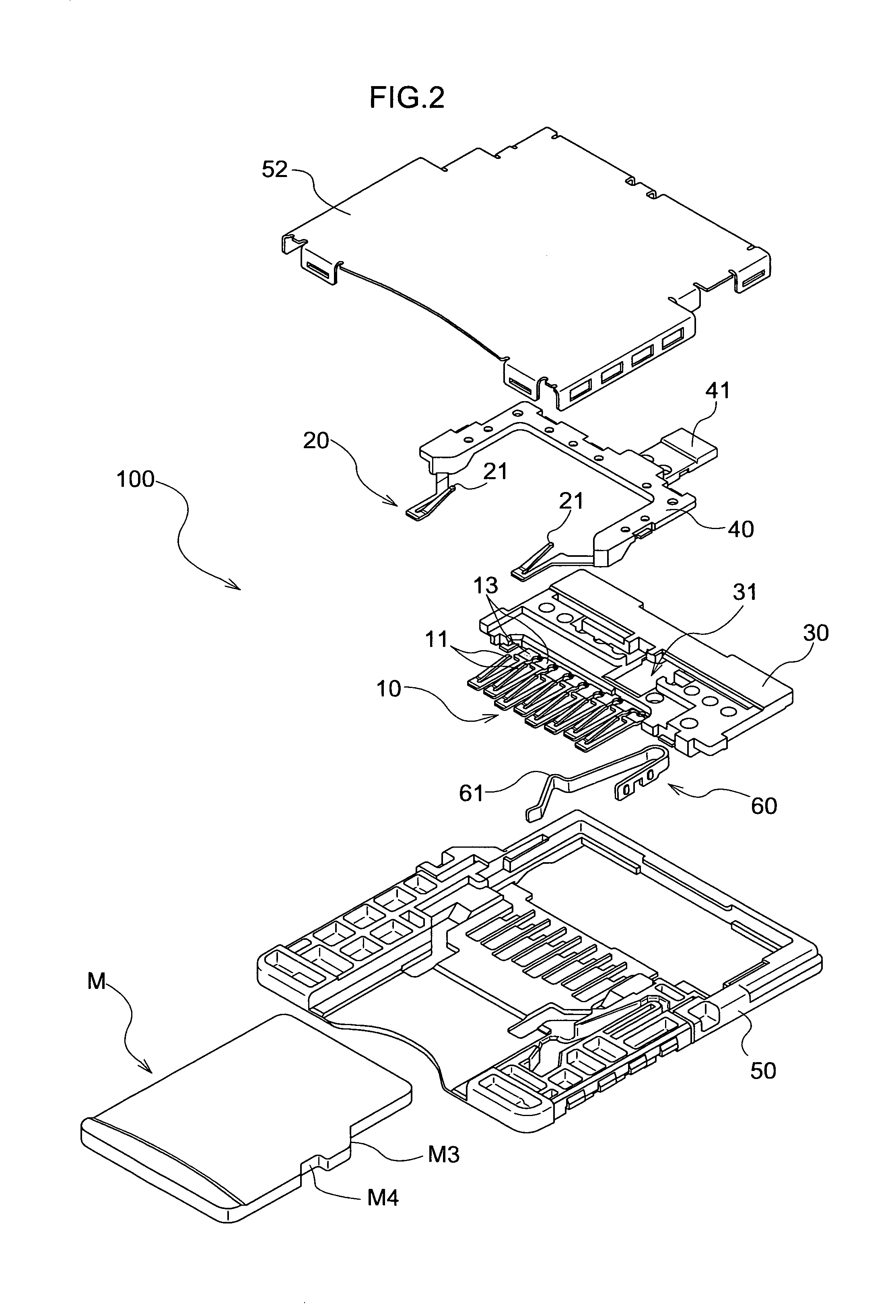
[0033]A card adapter 100 is used for connecting a memory card M having the first electrode array M1 and the second electrode array M2 shown in FIG. 3, to connectors (not shown) provided in electronic devices (not shown) for other memory cards which are different from the memory card M. The present invention can be applied to any combination of the memory card M and a connector of electronic devices.

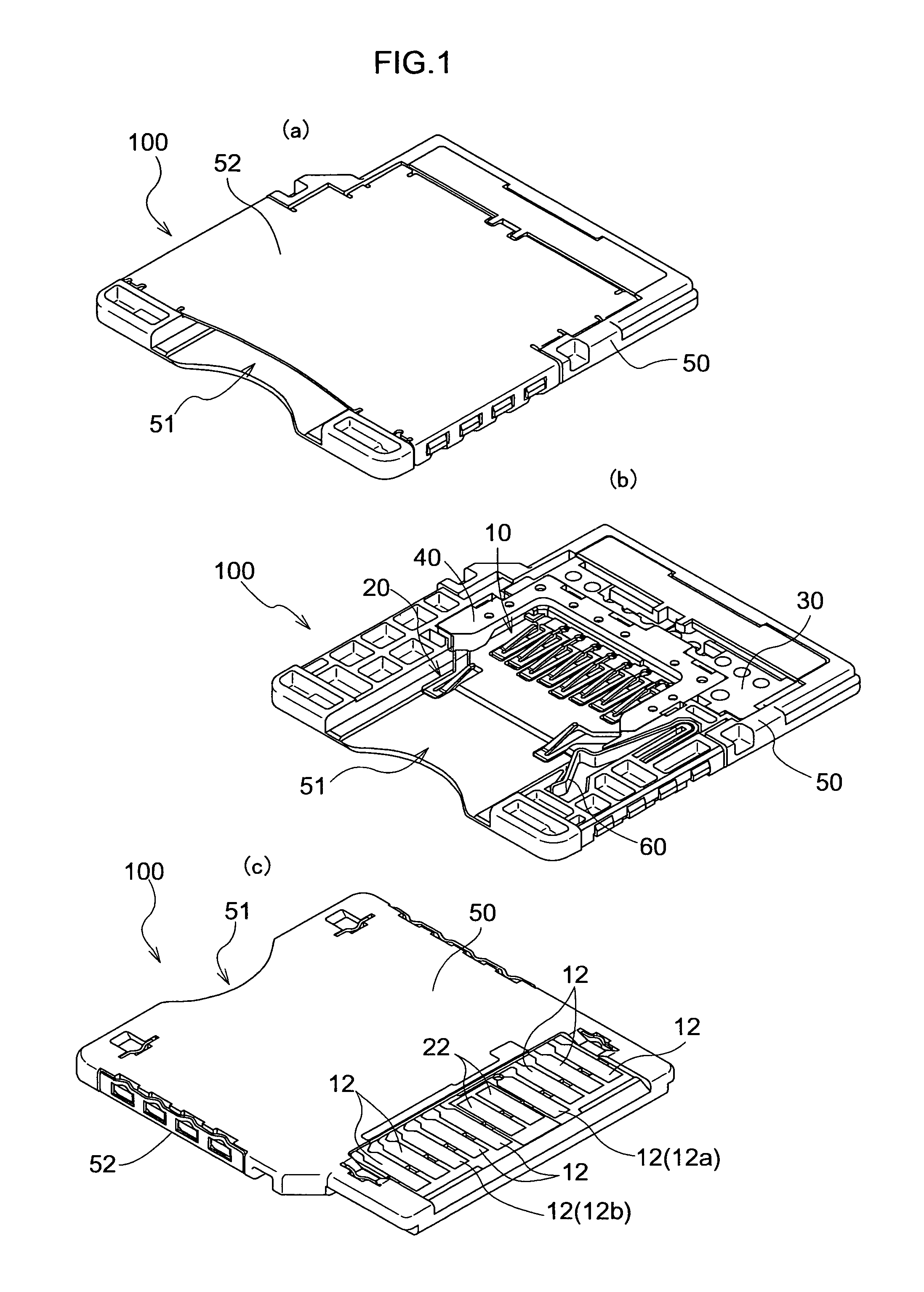
[0034]As shown in FIG. 1, the card adapter 100 comprises a main body 50 having an insertion slot 51 formed for inserting the memory card M. Insulating materials, such as resin is molded to form the main body 50, as shown in FIG. 4. Two groups of contact members, the first contact member 10 shown in FIGS. 1 and 5 and the second contact member 20 shown in the F...


PUM


Abstract

A card adapter comprises a main body (50) having an insertion slot (51) into which a memory card (M) is inserted; a first contact member (10) having first contact points (11) for contacting a first array of electrodes (M1) and first connecting portions (12) to be connected to a connector with base portions (13) located between the first contact points (11) and the first connecting portions (12); a second contact member (20) having second contact points (21) for contacting a second array of electrodes (M2) and second connecting portions (22) to be connected to a connector with base portions (23) located between the second contact points (21) and the second connecting portions (22); the first contact member (10) and the second contact member (20) being arranged within the main body (50) in such a way that the first contact points (11) and the second contact points (21) are located at different positions in a direction to which the memory card (M) is inserted.

Description

CROSS REFERENCE TO RELATED APPLICATIONS[0001]Priority based on JP2006-338492, which was filed by the applicant on Dec. 15, 2006 in Japan is claimed in this application, and the entire application is incorporated by reference in this application.THE BACKGROUND OF THE INVENTION[0002]1. The Field of the Invention[0003]The present invention relates to a card adapter used for connecting a memory card to a connector for other memory cards.[0004]2. Description of Related Art[0005]For instance, storing image data taken by digital cameras and music data downloaded from music distribution sites onto memory cards as a recording medium for utilizing them with a variety of electronic devices is becoming part of everyday life. Many types of memory cards with different sizes and construction are sold in the market. However, an electronic device can only accept a memory card complying with a particular standard, for example, a memory card compatible with the connector of the electronic device. Ther...

Claims


Application Information

Patent Timeline
Patent Type & Authority Patents(United States)
IPC IPC(8): H01R24/00
CPCG06K7/0021H01R13/2442H01R13/5045H01R31/06H01R12/714H01R13/514Y10S439/945H01R43/24H01R13/65802H01R13/6583
Inventor TANAKA, AKIHIRONAKAI, YASUO
Owner HOSIDEN CORP
Why Eureka
Try Eureka