Head gimbal assembly with dual-mode piezo microactuator

a microactuator and head gimbal technology, applied in the direction of maintaining the head carrier alignment, recording information storage, instruments, etc., can solve the problems of affecting the shock absorption capacity of the suspension, affecting the dynamic performance, and affecting the known relative locations of the load beam, etc., to achieve the effect of dampening vibration

Active Publication Date: 2008-08-26
MAGNECOMP
View PDF49 Cites 67 Cited by
  • Summary
  • Abstract
  • Description
  • Claims
  • Application Information

AI Technical Summary

Benefits of technology

[0015]In this and like embodiments, typically, the adhesive agent allows microactuator dimensional change that does not expand the gap, the mount plate has a first portion and a second portion, the first and second portions jointly defining a locus of attachment and a locus of separation, the adhesive agent flexibly binding the first and second portions together at their locus of separation, and the adhesive agent is arranged on the mount plate to dampen vibrations.

Problems solved by technology

The known relative locations of the load beam, hinge and microactuator body have been problematic.
Physical separations, however, among the actuator body, hinge and stiffener parts form discontinuities (voids) in the suspension adjacent the mount plate that degrade the dynamic performance, i.e. lower modal frequencies, and adversely affect the shock absorption capabilities of the suspension.
Further, asymmetry of mass about the longitudinal axis can cause out-of-plane vibration modes to flare up, as will similarly having the actuation plane not in plane with the mount plate.
Stiffeners, provided to improve the shock and dynamic performance of the head gimbal assembly HGA, can, when typically placed distally of the PZT mechanically block the PZT, thus attenuating the mechanical amplification (leverage) inherent in the structure, limiting the attainable stroke levels of the system.

Method used


Image

  • Head gimbal assembly with dual-mode piezo microactuator
  • Head gimbal assembly with dual-mode piezo microactuator
  • Head gimbal assembly with dual-mode piezo microactuator

Examples


Embodiment Construction

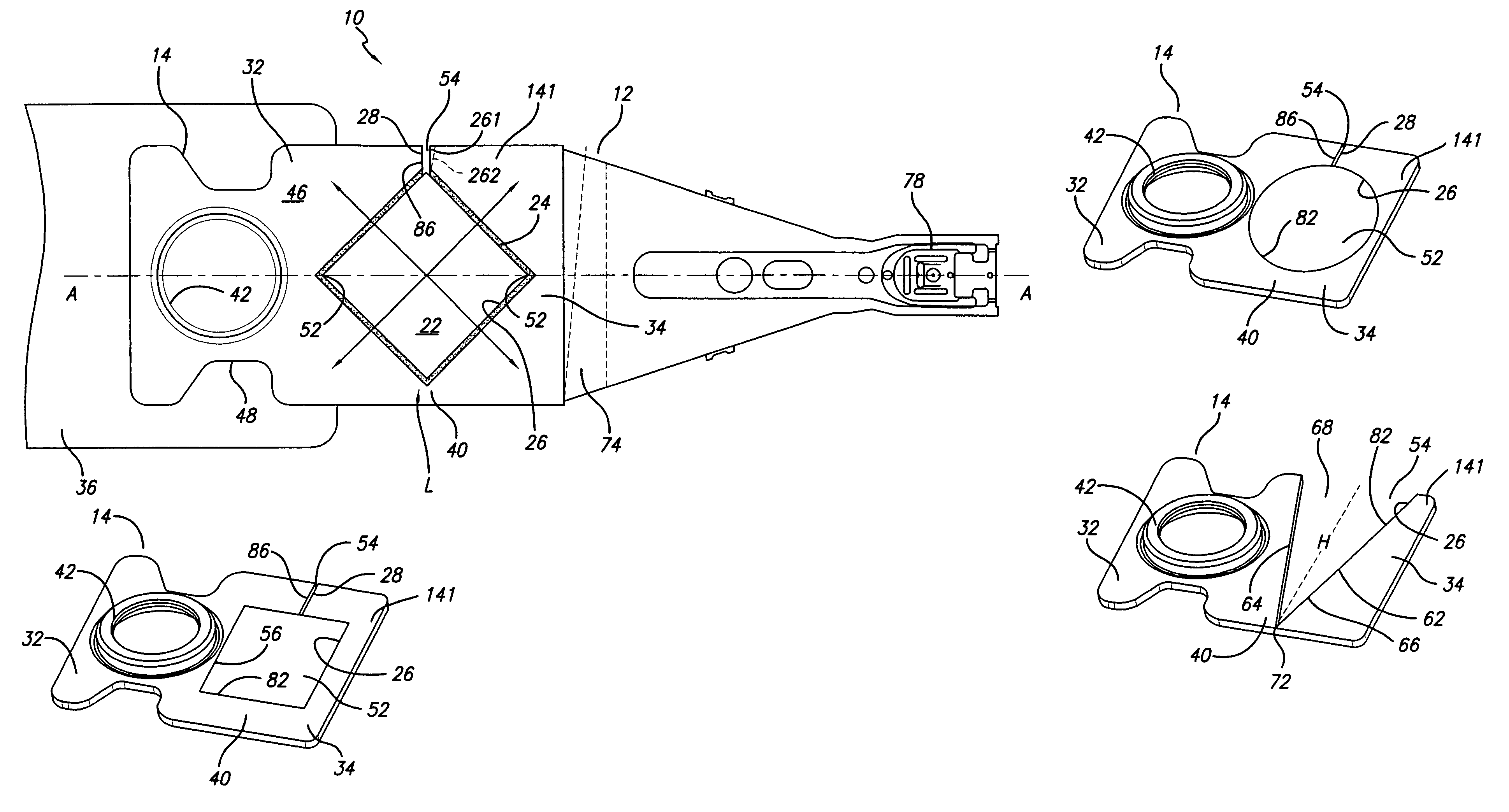
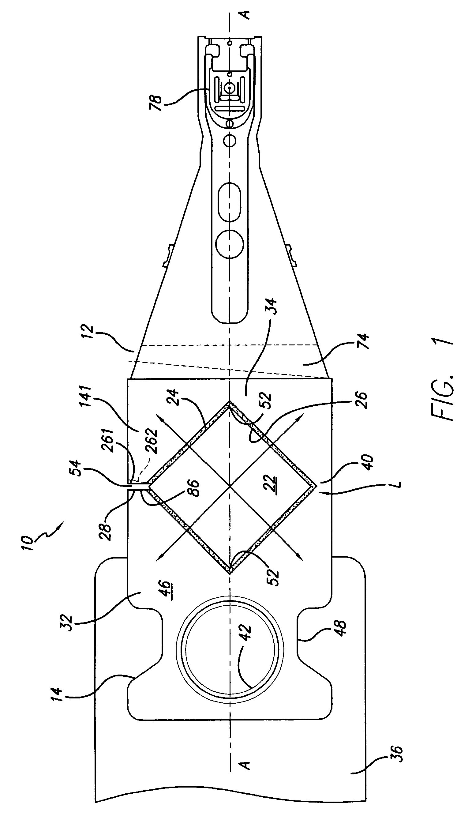
[0029]In accordance with the invention, a breathing-mode piezo microactuator is embedded in parallel or in plane with the mount plate of the suspension. All four vertical sides (vertical edges or horizontal edge margins) of the PZT are engaged to the mount plate via adhesives and work in tandem both in the d31 and the d32 modes, i.e. lengthwise and widthwise, see arrows in FIG. 1.

[0030]With reference now to the drawings in detail, in FIGS. 1-11 the invention disk drive suspension 10 comprises a load beam 12 and a mount plate 14 in operative association for carrying a slider 18 (FIG. 6) at a disk surface (not shown), and a microactuator 22 arranged to locally shift the mount plate and the load beam thereby in corresponding relation over a disk surface.

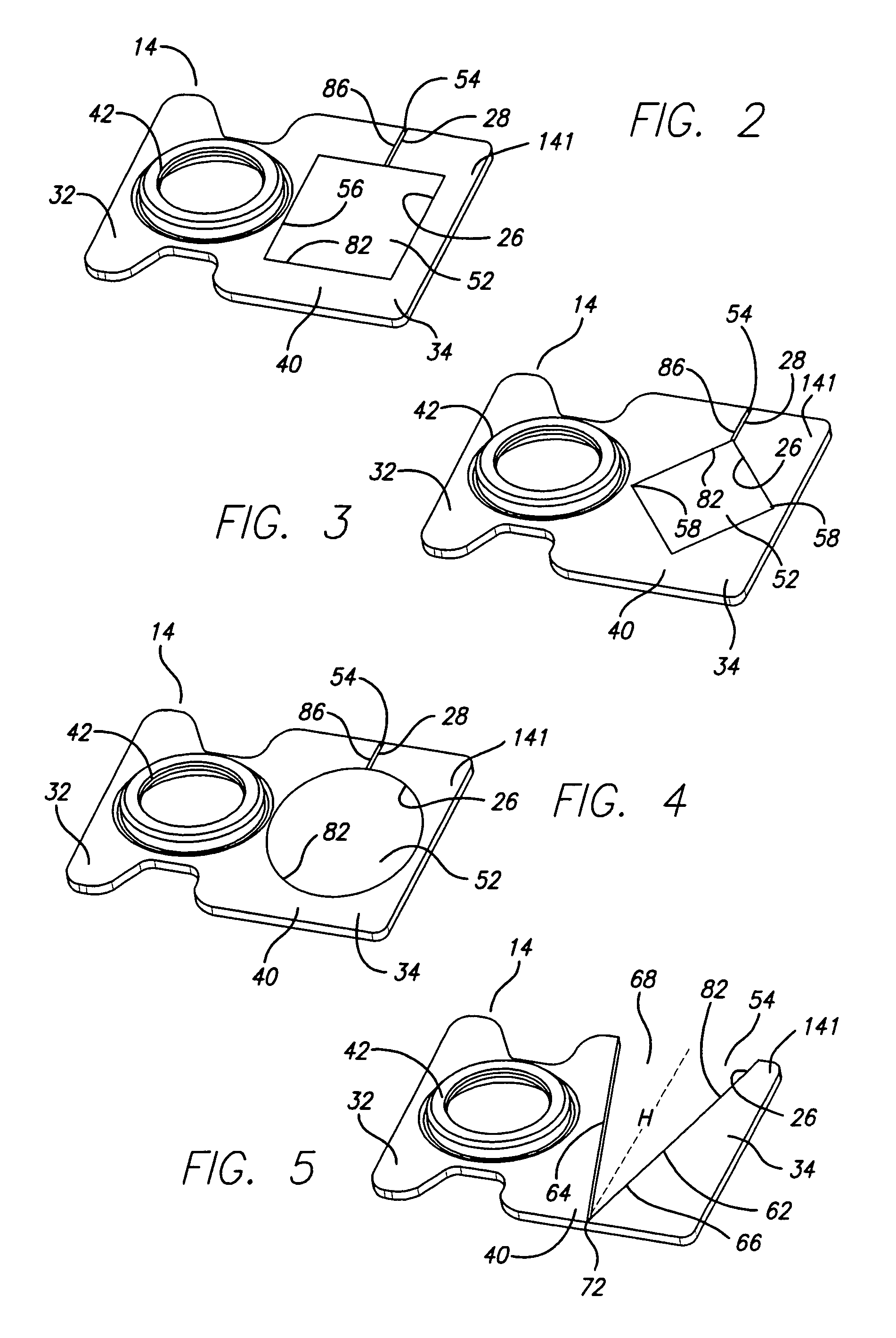
[0031]Microactuator 22 and mount plate 14 can be coplanar (FIGS. 6-8 and 10-11), or in parallel planes (FIG. 9). Mount plate 14 can be rigidly fixed to the microactuator 22 with an adhesive or bonding agent 24 whereby the mount plate te...


PUM

PropertyMeasurementUnit
sizeaaaaaaaaaa
perimeteraaaaaaaaaa
gap sizeaaaaaaaaaa

Abstract

A disk drive suspension has a load beam having a base, a flexure for carrying a slider, and a mount plate. The suspension mount plate has a first portion attachable to an actuator and movable by the actuator as the primary shifting force on the load beam, suitable for larger positioning movements. A second portion of the mount plate is attached to the load beam base and is movable relative to the mount plate first portion. A microactuator moves the second mount plate portion relative to the first mount plate portion as a secondary shifting force on the load beam, suitable for very small positioning movements.

Description

CROSS-REFERENCE TO RELATED APPLICATIONS[0001]This application claims the benefit of U.S. Provisional Application Ser. No. 60 / 712,999, filed Aug. 31, 2005.BACKGROUND OF THE INVENTION[0002]1. Field of the Invention[0003]This invention relates to disk drive suspensions having actuation and microactuation capabilities, and more particularly to suspensions in which the microactuation is effected by a microactuator acting on relatively movable portions of the suspension mount plate. In one embodiment, the suspension mount plate defines a pocket for the microactuator such that dimensional changes in the microactuator relatively shift connected portions of the mount plate to effect microactuated translation of the suspension load beam and flexure.[0004]2. Description of the Related Art[0005]Disk drive suspensions typically include a mount plate that is fixed to an actuator e.g. by staking, and the mount plate is attached to a load beam. The movement of the load beam by the actuator position...

Claims


Application Information

Patent Timeline
Patent Type & Authority Patents(United States)
IPC IPC(8): G11B5/56G11B5/596
CPCG11B5/4826G11B5/596G11B5/5552G11B5/4833G11B5/4873
Inventor KULANGARA, SIVADASAN
Owner MAGNECOMP
Why Eureka
Try Eureka