
Network quality estimation

a network quality and estimation technology, applied in the field of network quality estimation, can solve the problems of packet loss having the greatest effect on voice quality, packet loss may occur, packet loss is bursty in nature,

Active Publication Date: 2008-08-26
AVAYA INC
View PDF2 Cites 100 Cited by
  • Summary
  • Abstract
  • Description
  • Claims
  • Application Information

AI Technical Summary

Benefits of technology

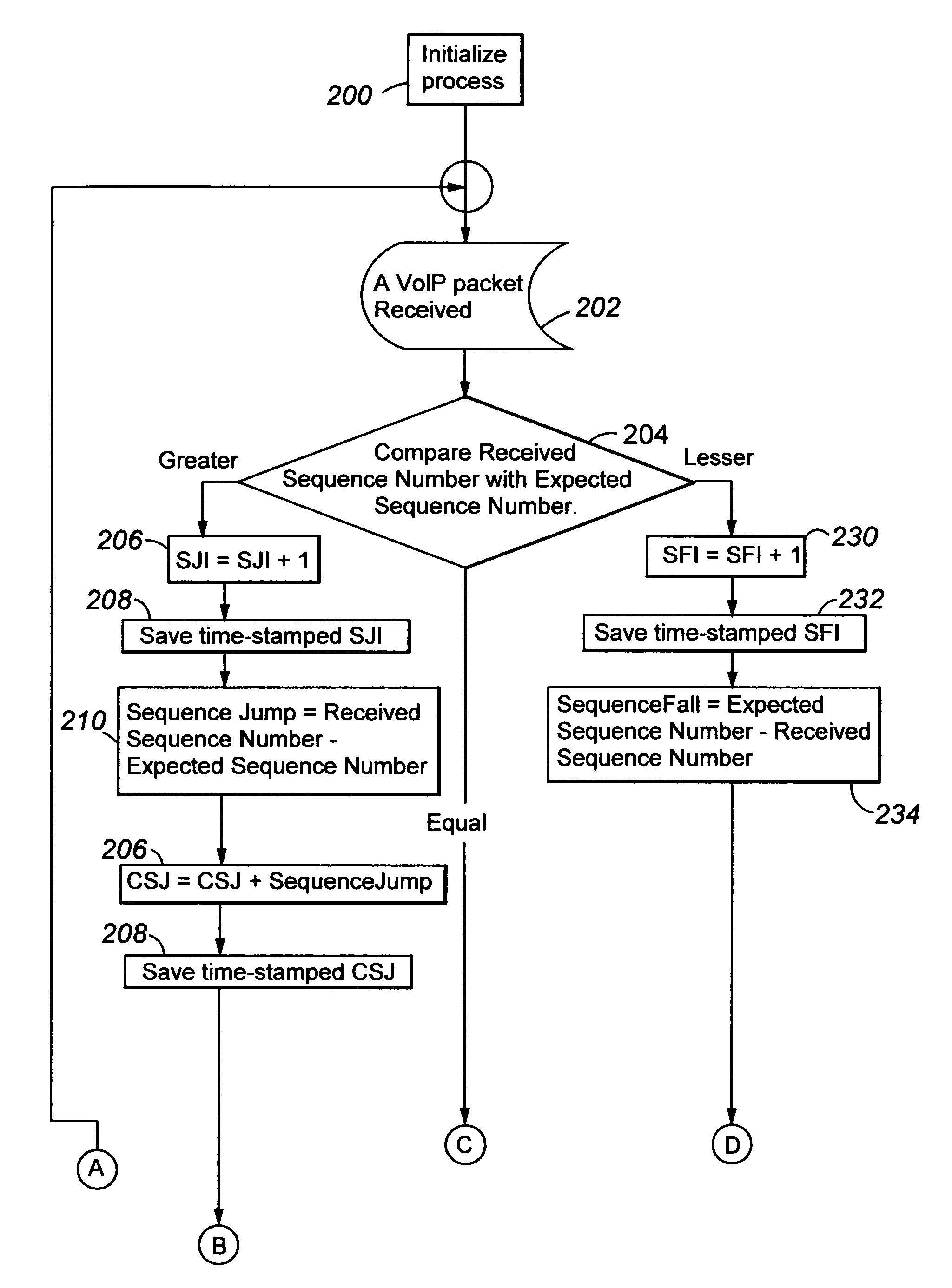
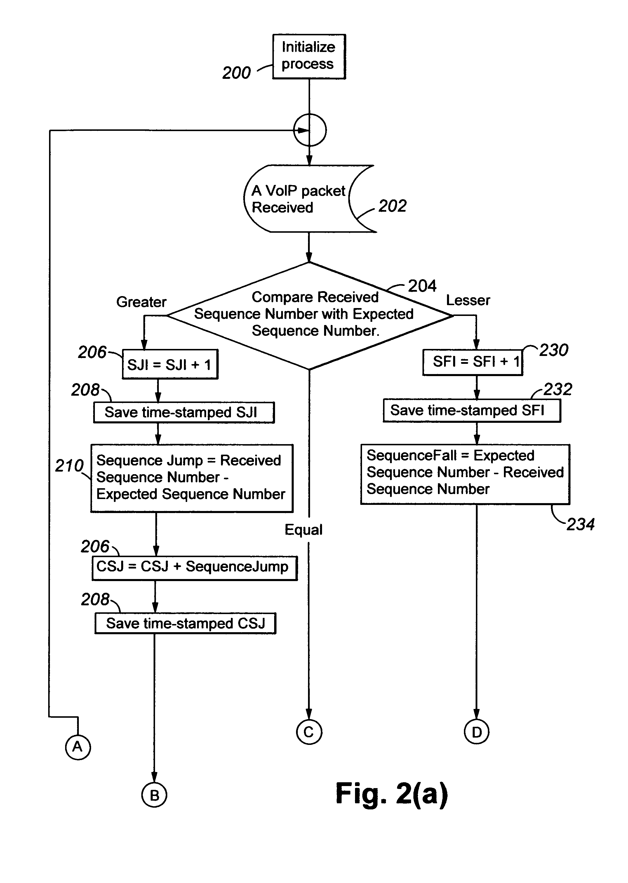
[0012]Preferably, a number of packets re-ordered on the connection is determined as a difference between the SFI at a beginning of an interval of time and the SFI at an end of the interval, and a number of packets lost on the connection is determined as a difference between (a) a difference between the CSJ at the beginning of the interval and the CSJ at the end of the interval and (b) the number of packets re-ordered during the interval. The invention provides information regarding packet loss, distribution of packet loss, packet re-ordering, and distribution of packet re-ordering, without requiring storage of a large amount of historical data regarding the packet stream. This makes the technique suited for use in embedded, low-cost, and high-channel-density VoIP devices. In addition to RTP, the invention is equally applicable to any packet protocol that uses packet sequence numbers or other mechanism that allows detection of missing packets in a packet stream.

Problems solved by technology

Packet loss has greatest effect on voice quality.
Packet loss may occur due to buffer overflow within the network, due to packets being deliberately discarded as a result of some congestion control scheme (e.g., Random Early Detection), or due to transmission errors.
Several of the mechanisms that can lead to packet loss are of a transient nature, and hence the resulting packet loss is bursty in nature.
However, the use of a jitter buffer compensates for jitter by increasing delay.
Bursty packet loss is far more detrimental to voice quality than random or evenly-distributed packet loss because packet-loss concealment algorithms are not capable of masking bursty packet loss.
Most VoIP systems report packet loss.
Although these metrics give an indication of packet loss, they do not provide enough information because they do not describe the characteristics of the loss, such as its distribution.
This is because packet-loss-concealment algorithms are not good at masking bursty packet losses.
Also, these RTP metrics provide no information for re-ordered packets and their distribution.
Compared to network characteristics such as loss or delay, the dynamics of packet reordering are far less-well understood.
A significant part of the problem is the lack of standard experimental techniques for measuring the phenomena.
Previous reordering studies have used measurement tools that are inherently biased, such as ping, or methodologies that scale poorly, such as analyzing multi-site packet traces.
The lack of a standard measurement methodology also has hampered the creation of a standard reordering metric.
Consequently, the results between different studies can superficially vary by an order of magnitude, thereby creating significant confusion and controversy about the prevalence of reordering.
The most obvious limitations of this approach arise from the use of the ICMP echo request / reply protocol for measurement.
Using this method, it is not possible to distinguish if a packet was reordered before it arrived at the remote host or after it left the remote host.
Consequently, the measurements produced can both underestimate the total reordering and overestimate the re-ordering in either direction.
Also, the use of ICMP as a fine-grained measurement tool is problematic since system and network operators alike increasingly filter and rate-limit such traffic to address security concerns.
This is principally because such reports require logging and maintaining of large amounts of historical data, which is a problem for low-cost devices, such as VoIP phones.
It is also a burden for devices that seek to maximize channel density with the least amount of hardware, and for devices that have limited processing power and data memory to process such large amounts of historical data.

Method used


Image

  • Network quality estimation
  • Network quality estimation
  • Network quality estimation

Examples


Embodiment Construction

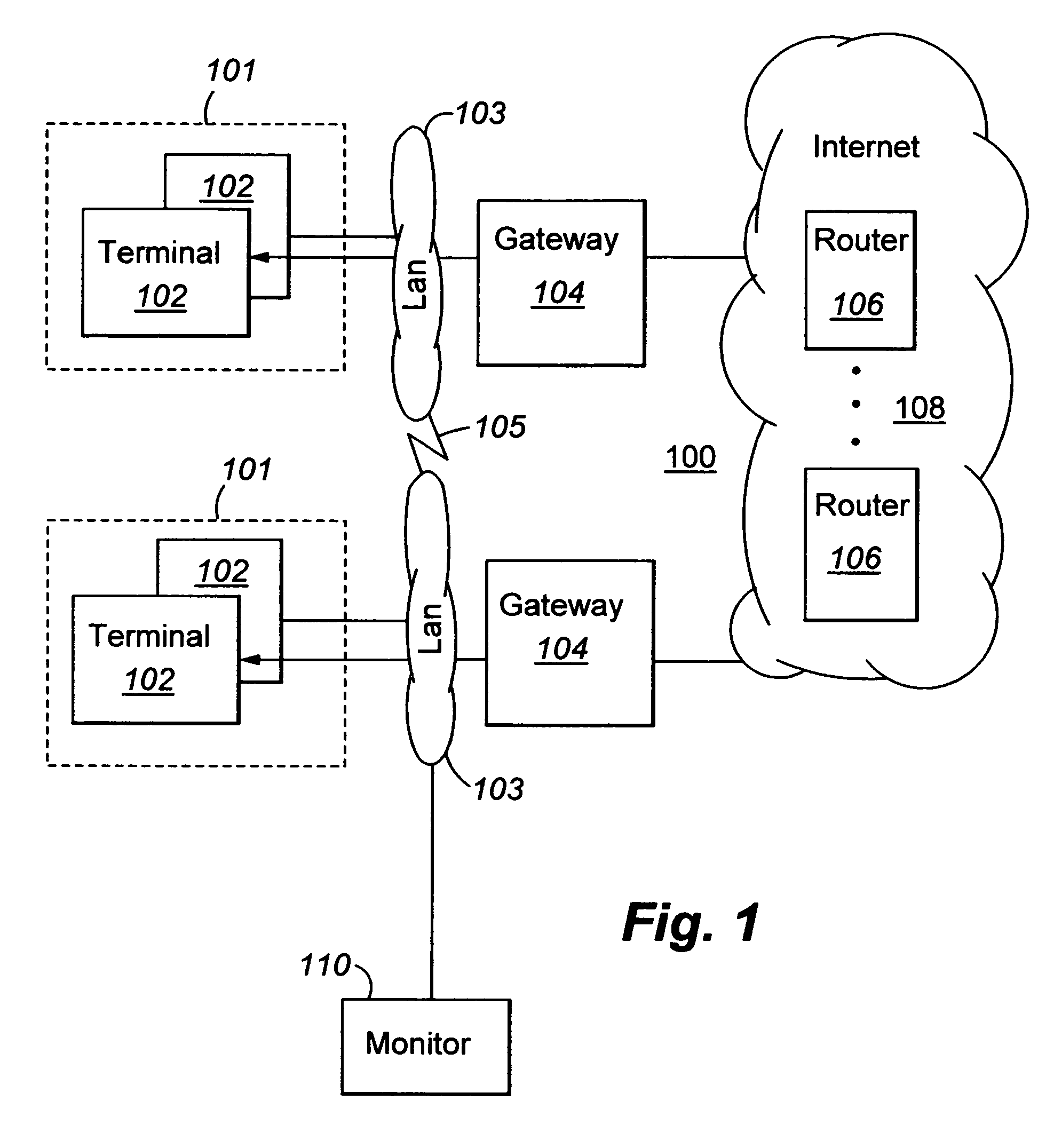
[0018]FIG. 1 shows a block diagram of a generalized packet transmission network 100. Packet transmission network 100 comprises a plurality of sets 101 of packet terminals 102 (for example, VoIP telephones). The terminals 102 of each set are interconnected with each other by a local area network (LAN) 103 and are connected by packet gateways 104 to a network of packet routers 106, such as internet 108. Additionally, LANS 103 may be directly interconnected by a wide area network (WAN) 105. One or more network-quality monitors 110 may be connected to one or more LANS 110. All elements 102, 104, 106, and 110 usually are stored-program-controlled devices that include storage for storing programs and data and processors for executing the stored programs and using the data, as well as hardware for performing their physical signal transmission, reception, and routing functions. The present invention is typically implemented in program form (as software) although it may be implemented in any...


PUM


Abstract

Disclosed are new calculations of packet loss bursts, packet re-ordering, and an indication of relative alternate network path delay metrics, based upon differences between received and expected packet sequence numbers, for determining packet network performance.

Description

TECHNICAL FIELD[0001]This invention relates to measuring and estimating the quality-of-service (QoS) provided by a packet transmission network.BACKGROUND OF THE INVENTION[0002]Certain transmissions, particularly real-time audio transmissions such as Voice over Internet Protocol (VoIP), are sensitive to the quality of the network connection over which they are being transmitted. Packet loss has greatest effect on voice quality. Packet loss may occur due to buffer overflow within the network, due to packets being deliberately discarded as a result of some congestion control scheme (e.g., Random Early Detection), or due to transmission errors. Several of the mechanisms that can lead to packet loss are of a transient nature, and hence the resulting packet loss is bursty in nature. A Markovian loss model suitably represents the distribution of packet loss in the Internet.[0003]Jitter (or packet-delay variation) also has an effect on voice quality. However, the use of a jitter buffer comp...

Claims


Application Information

Patent Timeline
IPC IPC(8): H04L12/28H04L12/56
CPCH04L41/5009H04L41/5087H04L47/34H04L43/10H04L45/123H04L43/0835
Inventor CRAWFORD, JAMESHEPWORTH, NEILKIM, BHUM CHULMINHAZUDDIN, MUNEYBSCHOLTE, ALEXANDER
Owner AVAYA INC
Learn More