
Double klap flex base boot with heel linkage

a flexible, boot technology, applied in the direction of skates, snowboard bindings, skating parts, etc., can solve the problems of reducing the efficiency of thrust transfer, reducing the comfort of skaters, increasing friction, and reducing skaters' speed, so as to achieve more power and speed, reduce friction, and be lighter in weigh

Inactive Publication Date: 2008-09-02
K 2 CORP
View PDF81 Cites 21 Cited by
  • Summary
  • Abstract
  • Description
  • Claims
  • Application Information

AI Technical Summary

Benefits of technology

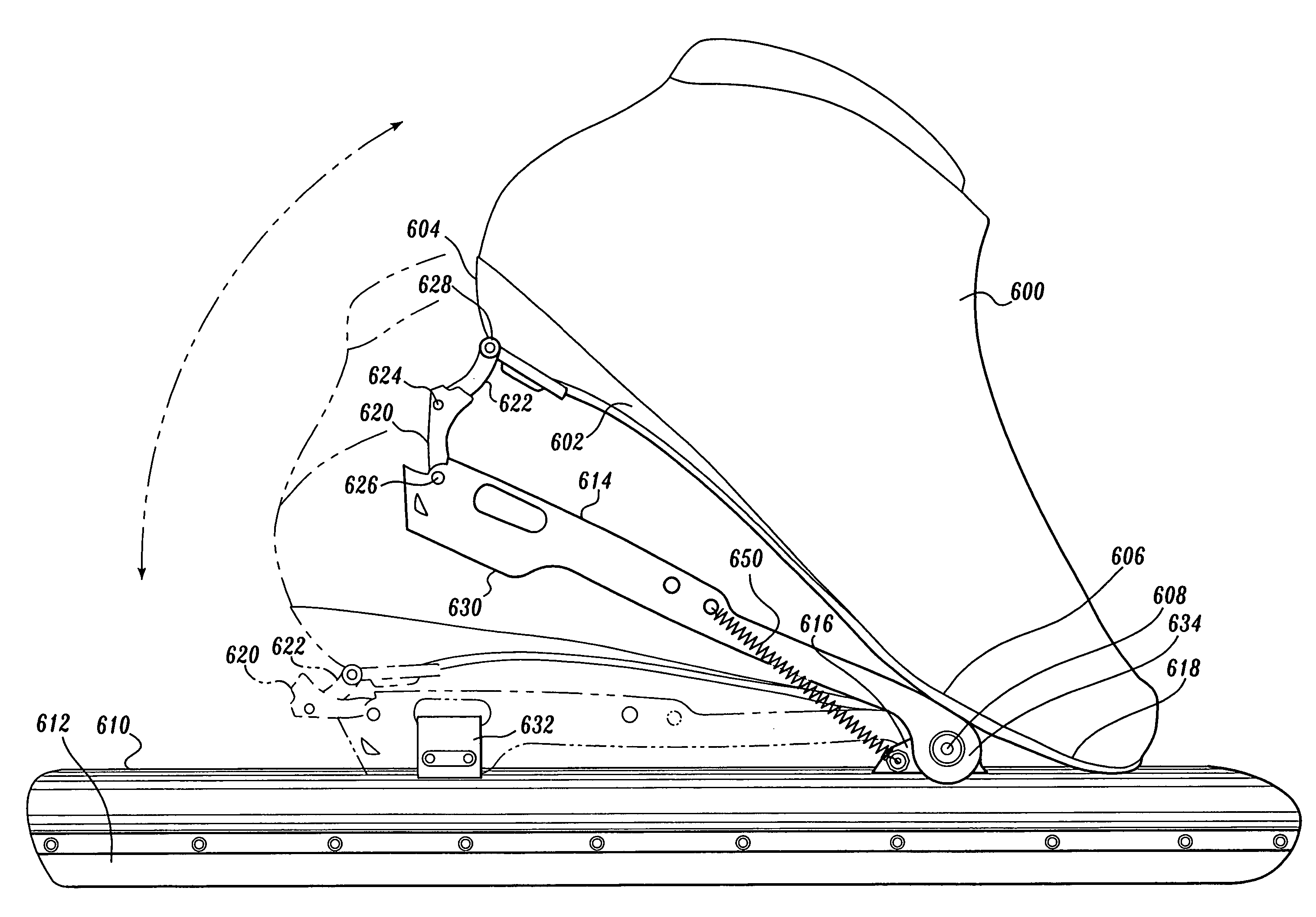
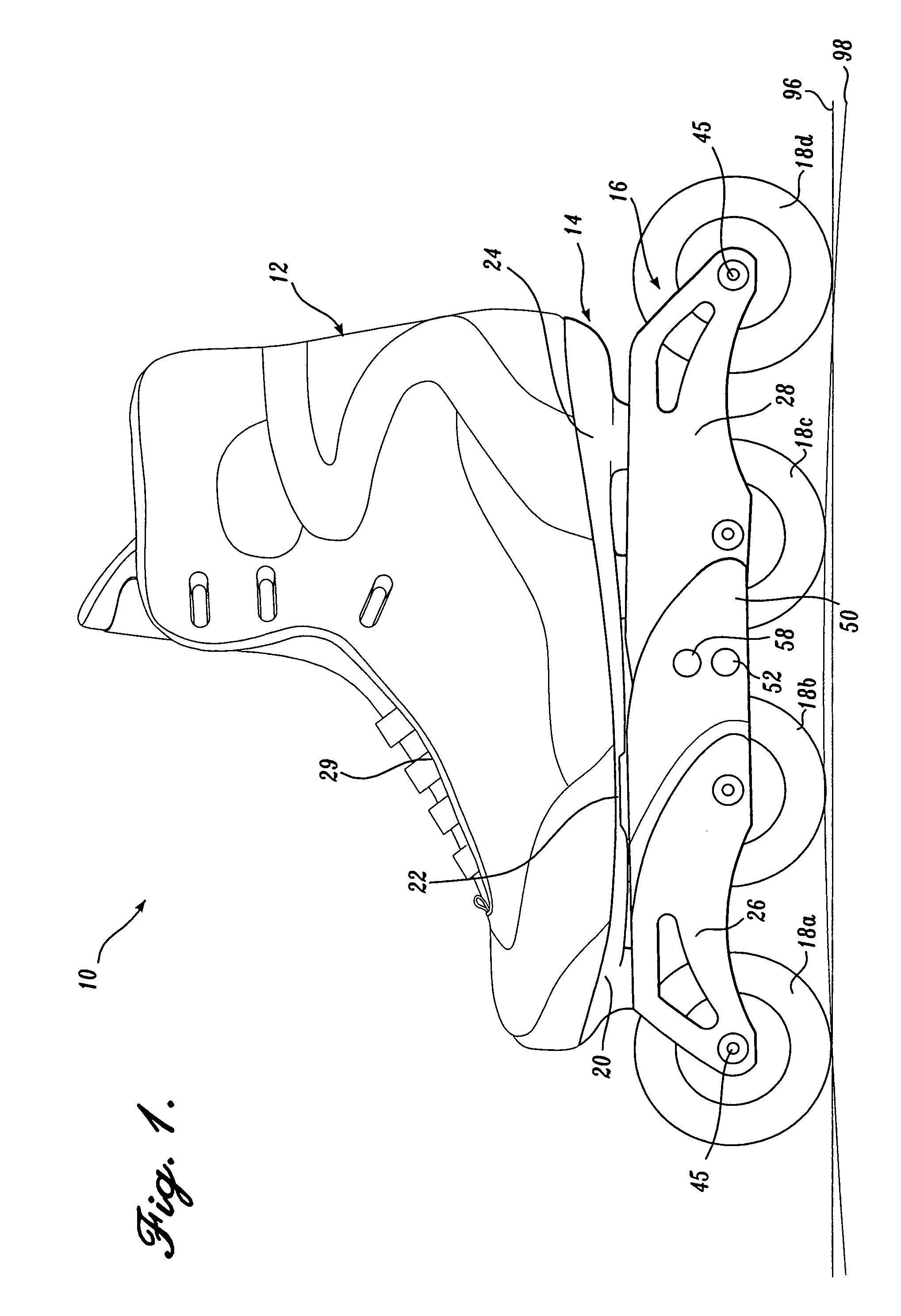
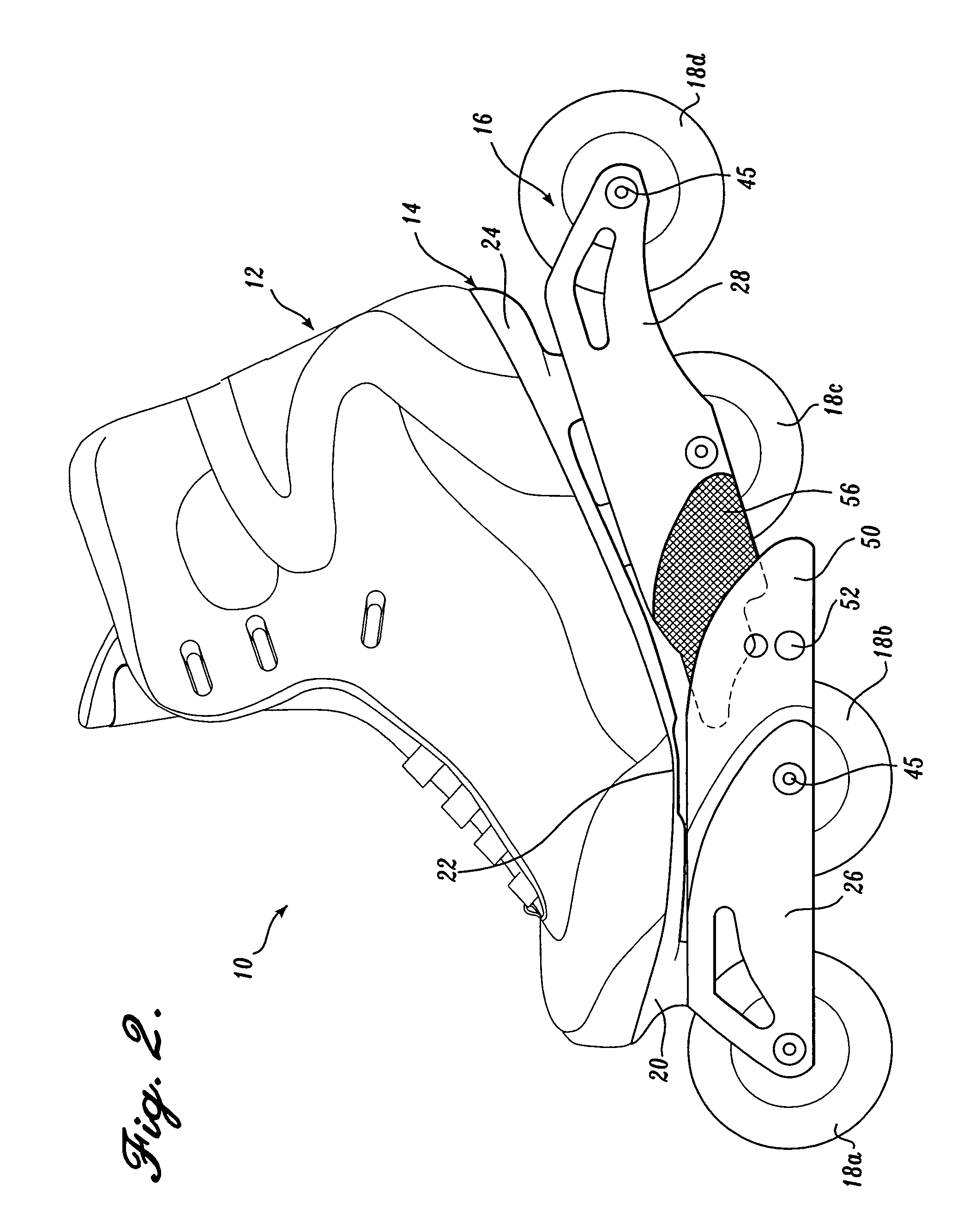
[0010]The present invention relates to a skate boot that is hingedly attached to an elongated bearing member capable of traversing a surface. The boot has an upper shoe portion adapted to receive a foot and a sole defining a heel end, a metatarsal portion having a metatarsal head area, and a toe end. The boot further includes a first hinge member defined in the metatarsal portion thereof to permit the boot to flex in the metatarsal region while the toe end remains substantially parallel with a horizontal plane defined by the bearing member. The boot also includes a second hinge member attached to the sole of the boot, near the toe end, that hingedly attaches the boot to the bearing member. The second hinge member defines a second pivot point, such that as the boot hinges at the second hinge member and about a lateral axis defined relative to the longitudinal direction of the bearing member, the skater is able to push-off from the second hinge member. The boot also includes an elongate frame that is disposed between and attaches the sole of the boot to the bearing member. The skate further includes a third hinge member that connects the rear of the sole of the boot to the rear of the bearing member. The third heel hinge provides lateral stability to the rear of the boot.
[0011]In a first embodiment, the upper surface of the frame defines an upwardly projecting mid-boot mount adapted to support the boot at a predetermined location near the metatarsal head area of the sole. The embodiment includes an elongate support plate having a forward end hingedly connected to the frame and a rearward end that extends at least to behind the metatarsal head area of the sole. The mid-boot mount engages the support plate near the metatarsal head area, thereby providing stable support for the support plate. In the embodiment, the mid-boot mount engages the support plate behind the metatarsal head area.
[0014]The skate of the present invention provides several advantages over currently available skates. The skate of the present invention provides a first hinge member defined in the metatarsal head area of the upper shoe portion and a second hinge member that pivotally attaches the skate to the skate frame. The first and second hinge members permit the skate to flex in both the metatarsal head area and the toe area of the boot. The skate of the present invention also has the added advantage of permitting the ankle to plantarflex and the fore foot to flex during the skate stroke, thereby permitting a skater to generate more power and, thus, speed. Additionally, plantarflexion prevents the tip of the blade from digging into the ice during the skate stroke. The skate of the present invention is also lighter in weight than those currently available. These advantages combine to define a skate having a double-hinge attachment design to permit skaters to plantarflex their ankle and to flex and extend their toes to generate more power and speed without the tip of the blade digging into the ice.

Problems solved by technology

When skating on traditional skates, particularly during thrusting, difficulties are encountered in efficiently transferring the thrust from the skater to the ground.
The inefficiencies are due in part, to the frame being rigidly attached to the base of the skate, which decreases the effectiveness of the thrust, as well as the comfort for the skater.
No plantarflexion at the ankle keeps the blade flat on the ice and prevents the tip of the blade from digging into the ice, thereby causing an increase in friction and reducing the skater's speed.
Prior attempts at allowing ankle plantarflexion have resulted in complicated linkage mechanisms that move the instantaneous point of rotation between the boot and blade forward as the heel lifts.
Such a linkage mechanism often results in a skate that is too heavy because of the multiple links.
While a single-hinge point attachment system is lighter, current models fail to prevent medial to lateral motion of the blade relative to the boot when the heel is lifted because of a narrow hinge, thus resulting in an unstable skating stroke.
This produces an unstable platform from which the skater can apply thrust through the blade.
An additional drawback to skates having a single hinge joint stems from the shoe portion of the skate.
However, Allinger et al. failed to address the problem of lateral or sideways stability of the shoe in relation to the frame when the skater plantar flexes the ankle.
During the skating stroke involving plantar flexing, the heel of the shoe is moved up and away from the frame with the only attachment being at the front of the shoe, making the heel prone to lateral movement.
However, the construction of the skate described in the '744 patent makes it difficult to have control over which hinge flexes first.

Method used


Image

  • Double klap flex base boot with heel linkage
  • Double klap flex base boot with heel linkage
  • Double klap flex base boot with heel linkage

Examples


third embodiment

[0083]a flexing base skate 210 constructed in accordance with the present invention is illustrated in FIGS. 10 through 13. The skate 210 includes an upper shoe portion 212 that is mounted on and secured to a base 214 that is flexible below the metatarsal head of the skater's foot. The base 214 is secured to a split frame assembly 216 that extends longitudinally beneath the base 214 and rotatably connects to a plurality of wheels 218A, 218B, 218C, 218D between first and second opposing longitudinal sidewalls. The base 214 includes a forefoot region 220 having a metatarsal head portion 222 that underlies the metatarsal head of a skater's foot, and a heel region 224 underlying the skater's heel. The frame assembly 216 includes a forward frame segment 226 secured to the forefoot region 220 of the base 214, and a rearward frame segment 228 that is secured to the heel region 224 of the base 214.

[0084]The forward frame segment 226, rearward frame segment 228, and flexible base 214 cooperat...

first embodiment

[0085]Referring to FIGS. 10 and 11, the upper shoe portion 212 surrounds the toes, sides, heels, and ankle of a skater's foot and is constructed at least partially from flexible materials so that the upper shoe portion 212 will flex together with the base 214. The base 214 is best viewed in FIGS. 10 and 12. The base 214 is secured to the upper shoe portion 212 by any conventional method and may optionally include rigidizing ribs (not shown) similar to the ribs 41 described above. The flexibility of the metatarsal head portion 222 of the base 214 is enhanced by the formation of a transverse, elongate aperture 242 (shown in FIG. 12) that extends transversally and centrally across approximately half of the width of the metatarsal head portion 222, in exactly the same manner as the elongate aperture 42 described with respect to the first embodiment shown in FIG. 1. Thus, the base 214 and upper shoe portion 212 flex at the anatomically preferred position just below the metatarsal head or...

fourth embodiment

[0095]A greater number of wheels, such as five wheels, may be desired for greater speed. a flexing base skate 310, constructed in accordance with the present invention, is shown in FIGS. 14-17. The skate 310 includes an upper shoe portion 312 that is attached to a flexible base 314, having a forefoot region 320 that includes a metatarsal head portion 322, and a heel region 324. The base 314 is attached to a split frame assembly 316 that supports five wheels 318 that are rotatably mounted on axles 345. The forward frame segment 326 includes a horizontal top wall 331, two parallel side walls 332 depending vertically from the top wall 331, and a horizontal brace 327 to form a sturdy box frame structure. The rearward frame segment 328 similarly includes a horizontal top wall 334, two parallel sidewalls 336, and a horizontal brace 327, also forming a sturdy box frame structure. Three forward wheels 318 are rotatably journaled on axles 345 between the sidewalls 332 of the forward frame se...


PUM


Abstract

A skate includes a midskate hinge in the shoe to preferentially flex the shoe base at the metatarsal area, a forward hinge to allow the rear of the shoe to be raised in relation to the rear of the skate frame, and a third hinge to laterally stabilize the rear of the shoe as the shoe base is flexed.

Description

CROSS-REFERENCES TO RELATED APPLICATIONS[0001]This application is a continuation-in-part of U.S. patent application Ser. No. 10 / 743,428, filed Dec. 22, 2003, which is a continuation of U.S. patent application Ser. No. 10 / 188,737, filed Jul. 2, 2002, which is a continuation of U.S. patent application Ser. No. 09 / 632,453, filed Aug. 4, 2000, now abandoned, which is a continuation-in-part of U.S. patent application Ser. No. 09 / 094,425, filed Jun. 9, 1998, now U.S. Pat. No. 6,120,040, which is a continuation-in-part of U.S. patent application Ser. No. 08 / 957,436, filed Oct. 24, 1997, now U.S. Pat. No. 6,082,744. All the above applications are incorporated herein expressly by reference.FIELD OF THE INVENTION[0002]The present invention relates to klap skates and, more particularly, to klap skates with flexible shoe bases.BACKGROUND OF THE INVENTION[0003]Traditionally, in-line roller skates and ice skates generally include an upper shoe portion secured by a base to a frame supporting wheel...

Claims


Application Information

Patent Timeline
Patent Type & Authority Patents(United States)
IPC IPC(8): A63C1/00A63C1/28A63C17/06
CPCA63C1/28A63C17/067A63C17/065A63C17/062
Inventor HAUGEN, DARRIN JSVENSSON, JOHN E
Owner K 2 CORP
Learn More