Alignment method, method of measuring front to backside alignment error, method of detecting non-orthogonality, method of calibration, and lithographic apparatus

a technology of alignment error and alignment method, applied in the field of lithographic apparatus, can solve the problem of position error nevertheless remaining, and achieve the effect of accurate calculation and compensation

Inactive Publication Date: 2008-09-02
ASML NETHERLANDS BV
View PDF7 Cites 16 Cited by
  • Summary
  • Abstract
  • Description
  • Claims
  • Application Information

AI Technical Summary

Benefits of technology

[0018]In at least some arrangements of such an embodiment, non-orthogonality in the motion of the substrate table can therefore be accurately calculated and compensated for. It could, for example, be compensated for in software.

Problems solved by technology

Although considerable efforts are made to ensure that the positioning of the substrate during an exposure is as accurate as possible, position errors nevertheless remain.

Method used


Image

  • Alignment method, method of measuring front to backside alignment error, method of detecting non-orthogonality, method of calibration, and lithographic apparatus
  • Alignment method, method of measuring front to backside alignment error, method of detecting non-orthogonality, method of calibration, and lithographic apparatus
  • Alignment method, method of measuring front to backside alignment error, method of detecting non-orthogonality, method of calibration, and lithographic apparatus

Examples


third embodiment

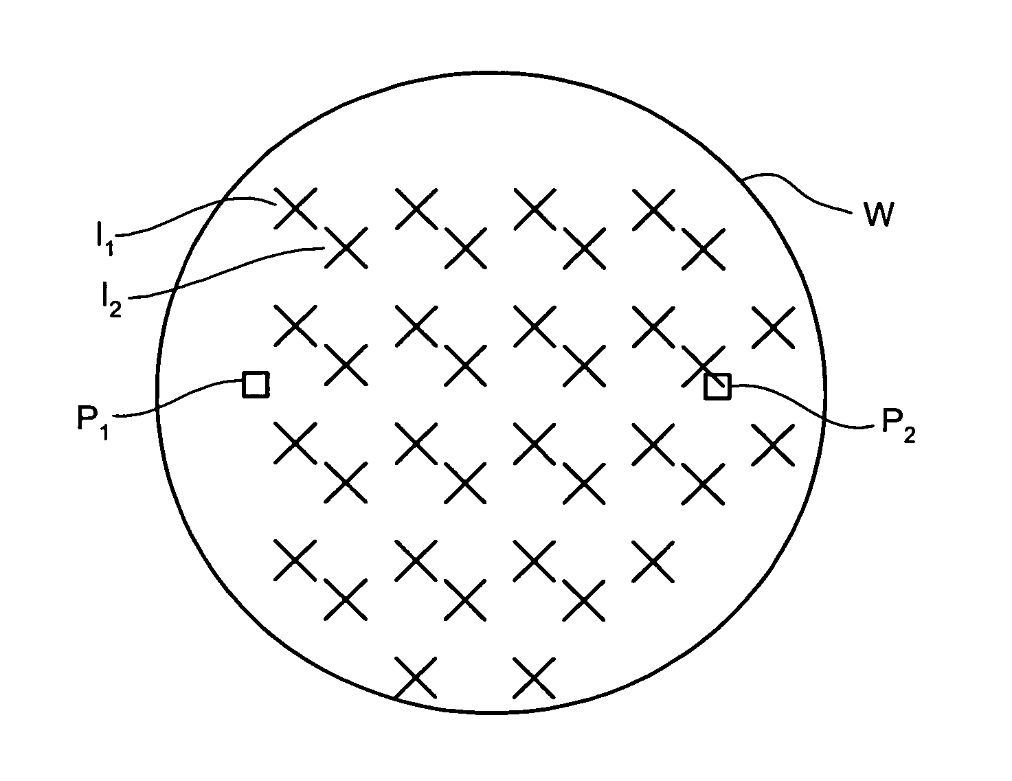
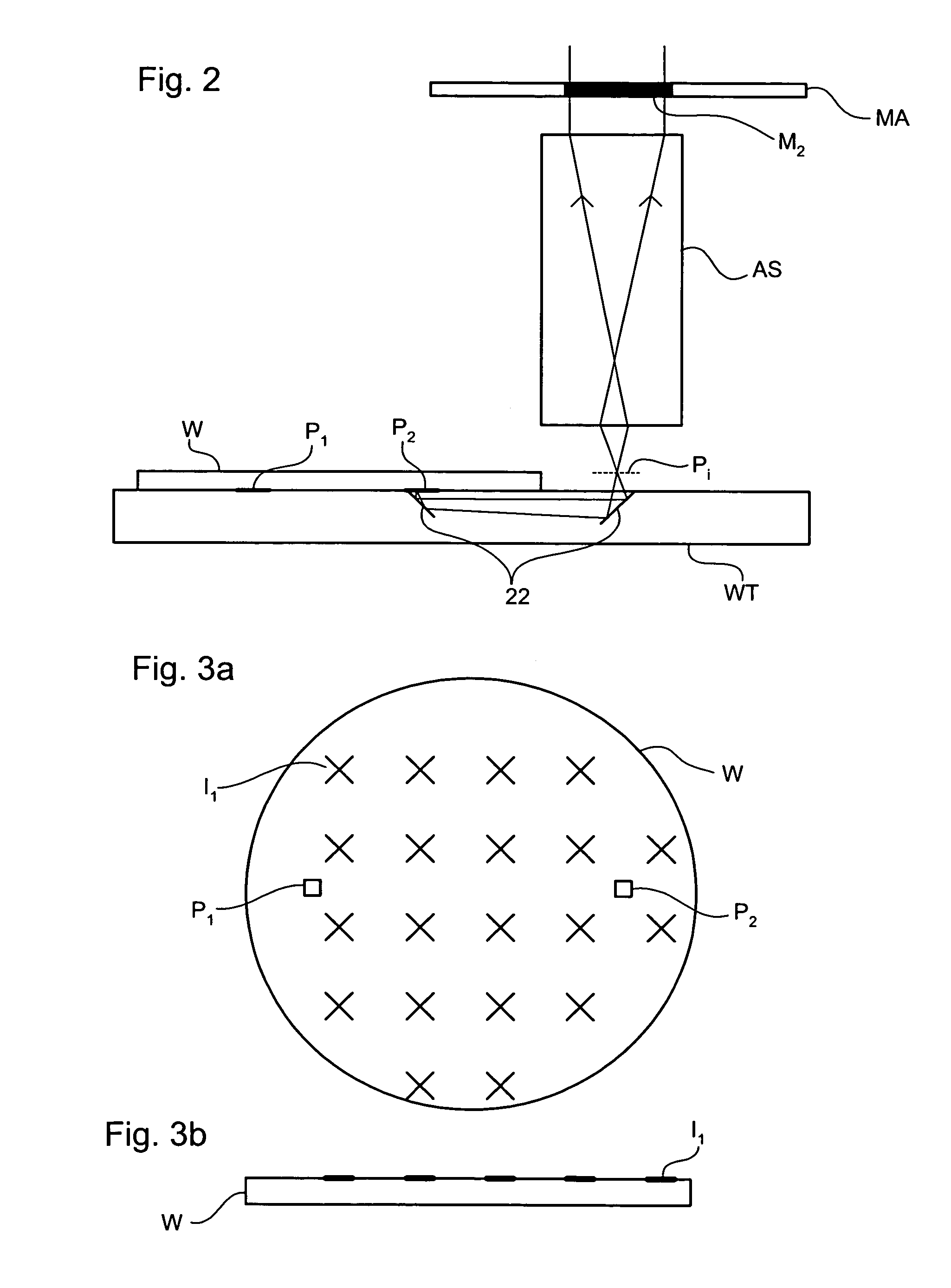
[0075]In a third embodiment, a transparent substrate W is etched with marks e1, e2, e3 and e4, each having mirror symmetry. As shown in FIG. 6 the line joining the centers of e3 and e4 is substantially perpendicular to the line joining the centers of e1 and e2.

[0076]An alignment system AS is then used to detect the location of e1. The substrate table WT is then moved to bring e2 to the focal point of the alignment system AS and the location of e2 detected. Next, the substrate table WT is moved to bring e3 to the focal point of alignment system AS and the location of e3 detected. This process is repeated again for mark e4.

[0077]As the directions in which the substrate table moves are not exactly orthogonal, the detected locations of e1, e2, e3 and e4 may lie along non-orthogonal lines as shown in FIG. 7A. This gives an indication of the non-orthogonality of the movement of the substrate table. However, if the line joining e3 and e4 on the substrate and the line joining e1 and e2 on ...

fourth embodiment

[0088]In a fourth embodiment, one layer of a device is printed at a plurality of locations, f1, f2, f3, f4 and f5, on a substrate as shown in FIG. 8. The substrate is then turned over and aligned using front to backside alignment optics and an alignment system AS. For each first layer of the device, f, a second layer of the device, g, is printed on the other side of the substrate. However, for each first layer of the device the second layer is offset in the y direction by a different amount. For example, the first second device layer, g1, is offset from the first first device layer, f1, by −200 nm. The second device layer, g1, is offset from the second first device layer by −100 nm. The third second device layer, g1, is not offset from the third first device layer. This pattern continues for all the devices and is shown in FIG. 9A.

[0089]The substrate is then removed from the lithographic apparatus and the performance of each of the five devices is tested and quantified. The performa...

fifth embodiment

[0092]In a fifth embodiment, a glass plate 31 with a reference mark 30 etched in aluminum is placed in the object window of front-to-backside alignment optics 35 as shown in FIG. 11. As shown in FIG. 12 the reference mark 30 is symmetrical in both the x and y directions. Alignment system AS detects reference mark 30 from above and through the front-to-backside alignment optics to determine the imaged optic vector. If the apparatus needs recalibrating at a later time the same glass plate can be used for calibration again.

[0093]Any discrepancies in the reference mark 30 between being read from above and being read from below (through front-to-backside alignment optics) can be determined using conventional calibration methods. The height of the substrate table may need to be adjusted between these two readings to ensure that the reference mark 30 is at the focal point of alignment system AS.

[0094]Alternatively, the reference mark 30 could be etched into the object window of front to ba...


PUM

PropertyMeasurementUnit
wavelengthaaaaaaaaaa

Abstract

In a method of measuring front to backside alignment error according to one embodiment, a transparent substrate has a plurality of marks on both the front and backside. The relative location of the marks on the front and backside of the substrate is determined to calculate the front to backside alignment error for the whole substrate. In a further embodiment, the substrate is rotated by 180° within the plane of the substrate and the front relative location of the marks is again determined.

Description

FIELD OF THE INVENTION[0001]The present invention relates to lithographic apparatus and methods of using such apparatus.BACKGROUND INFORMATION[0002]A lithographic apparatus is a machine that applies a desired pattern onto a target portion of a substrate. Lithographic apparatus can be used, for example, in the manufacture of integrated circuits (ICs). In that circumstance, a patterning structure, such as a mask, may be used to generate a circuit pattern corresponding to an individual layer of the IC, and this pattern can be imaged onto a target portion (e.g. comprising part of, one or several dies) on a substrate (e.g. a silicon wafer) that has a layer of radiation-sensitive material (resist). In general, a single substrate will contain a network of adjacent target portions that are successively exposed. Known lithographic apparatus include so-called steppers, in which each target portion is irradiated by exposing an entire pattern onto the target portion in one go, and so-called sca...

Claims


Application Information

Patent Timeline
Patent Type & Authority Patents(United States)
IPC IPC(8): G01B11/00G03C5/00G03F9/00
CPCG03F9/7003G03F9/7015G03F9/7088G03F9/7084G03F9/708
Inventor LOF, JOERIBIJNEN, FRANSISCUS GODEFRIDUS CASPERVAN BUEL, HENRICUS WILHELMUS MARIAKEIJSERS, GERARDUS JOHANNES JOSEPHSCHEEPENS, ROBERTUS VICTORIUS MARIA
Owner ASML NETHERLANDS BV
Why Eureka
Try Eureka