
Arranging packet data connections in office system

a packet data and office system technology, applied in the field of wireless office systems, can solve the problems of restricting the utilisation of different data services on both internal and external mobile connections, and the mobile station connected to an office system through an office-specific base transceiver station cannot utilise the services implemented by gprs, so as to save the capacity of public land mobile networks

Inactive Publication Date: 2008-09-02
NOKIA CORP
View PDF10 Cites 37 Cited by
  • Summary
  • Abstract
  • Description
  • Claims
  • Application Information

AI Technical Summary

Benefits of technology

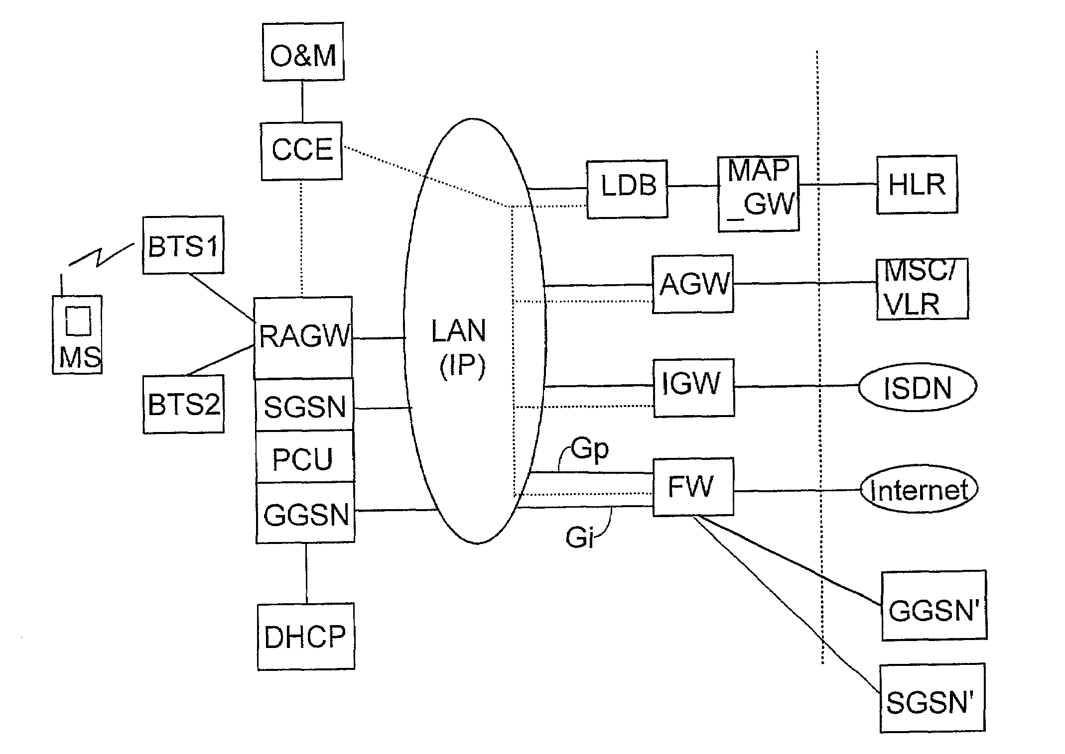
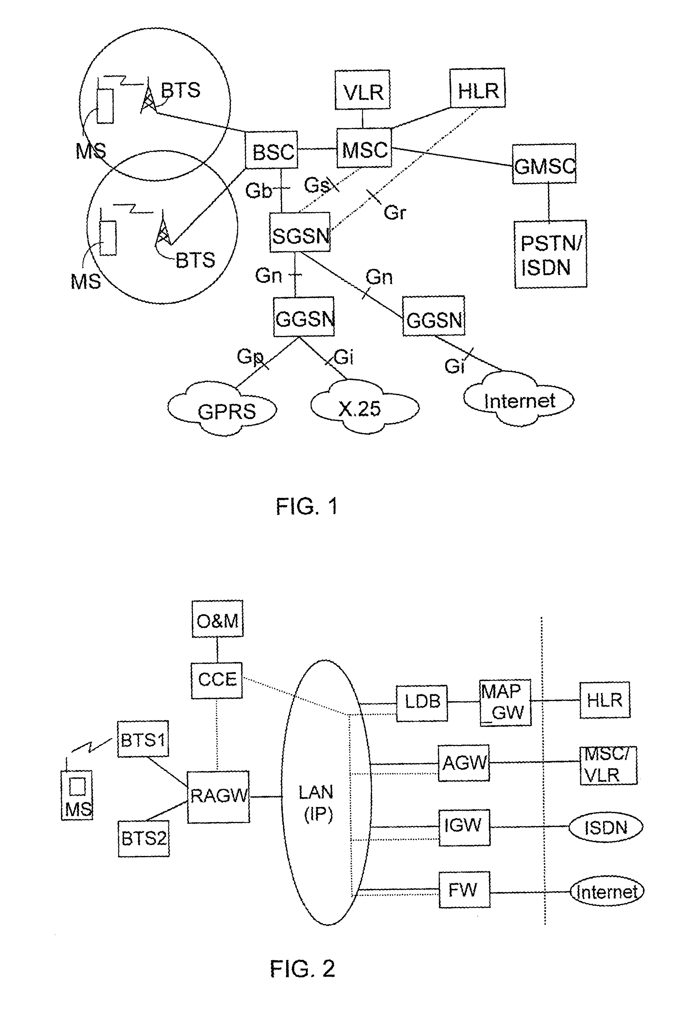
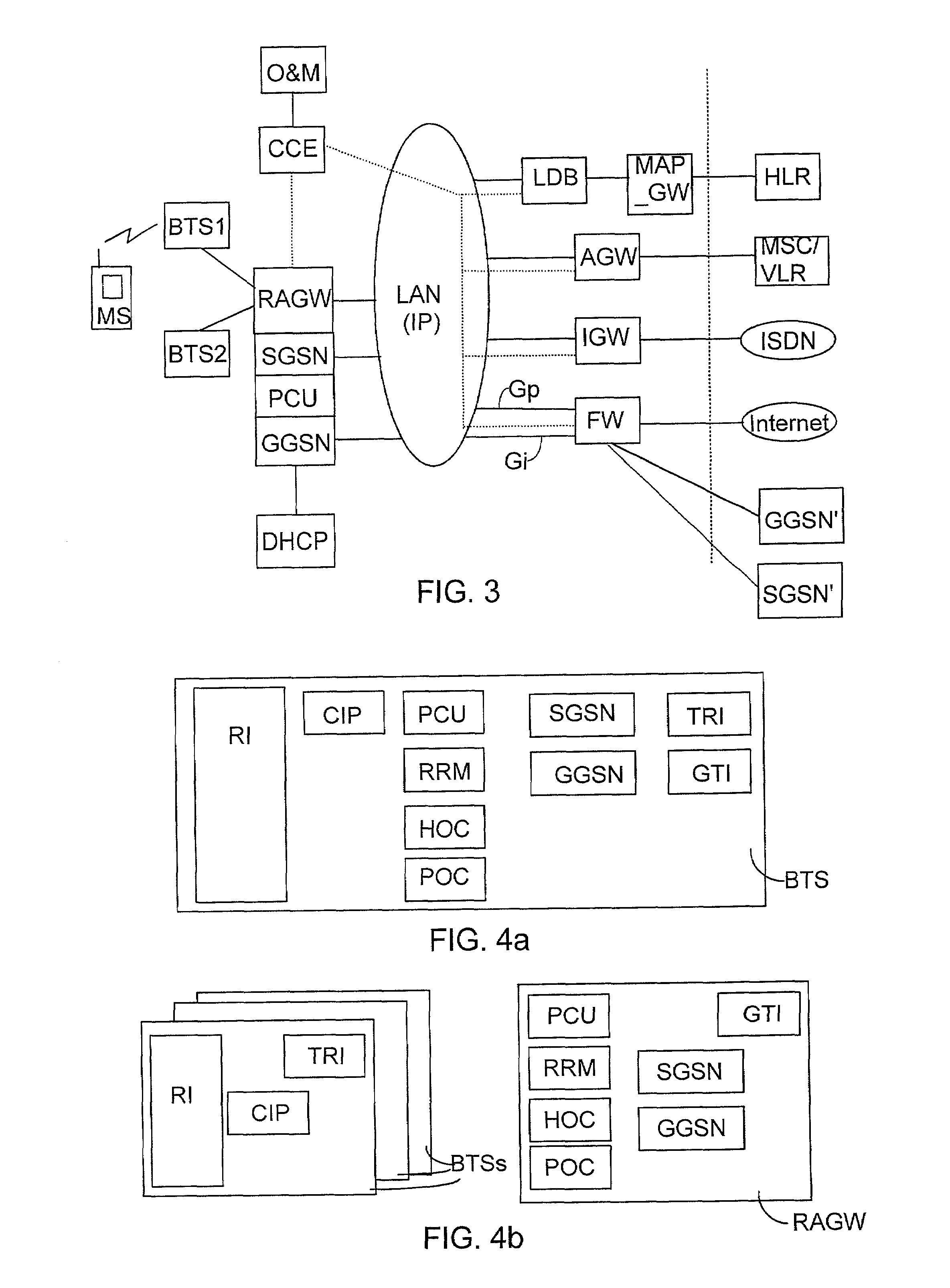
[0008]The method and arrangement of the invention provide the advantage that internal packet data connections of an office system can be established using the functions of the office system only, and the packet data connections, such as GPRS connections, need not be routed through a public land mobile network, such as the GSM network. This way, mobile stations in an office system can be provided with cheap, in practice free, packet data connections inside the office system, and the links can, if necessary, be encrypted specifically for each office system. In addition, packet data capacity of the public land mobile network is saved, since the internal packet data connections of an office system need not be routed through the public network.

Problems solved by technology

A problem with the arrangement described above is that the office system is arranged to route only circuit-switched speech connections to or from the mobile station.
A mobile station connected to an office system through an office-specific base transceiver station cannot utilise services implemented by GPRS, because the typical office-specific base transceiver station BTS described above does not comprise an interface to the GPRS system and thus does not support GPRS protocol layers.
This restricts the utilisation of different data services on both internal and external mobile connections of an office.

Method used


Image

  • Arranging packet data connections in office system
  • Arranging packet data connections in office system
  • Arranging packet data connections in office system

Examples


Embodiment Construction

[0018]In the following, the invention will be described by way of example on the basis of the GSM system and the GPRS system connected to it. An office system of the invention can, however, also be implemented to any other mobile system which comprises packet data functions essential for the implementation of the invention. This invention can be applied to the third-generation mobile system UMTS (Universal Mobile Telecommunication System), for instance, which comprises functions corresponding to the GPRS system.

[0019]FIG. 1 illustrates how the GPRS system is built on the GSM system. The GSM system comprises mobile stations (MS) which have a radio connection to base transceiver stations (BTS). Several base transceiver stations BTS are connected to a base station controller (BSC) which controls the radio frequencies and channels available to them. The base station controller BSC and the base transceiver stations BTS form a base station subsystem (BSS). The base station controllers BSC...


PUM


Abstract

A method for establishing a packet data connection in a telecommunications system which includes an office network, an operator network, and a local area network between them. Data transmission from the office network through the local area network is adapted to a data transmission protocol according to a mobile system. The office network also includes a serving support node, a packet control unit, and a gateway support node, which are arranged to support the packet data protocol of the mobile system. The serving support node, packet control unit, and gateway support node are arranged to have a functional connection with each other and with a radio access gateway. A packet data connection request is made from a mobile station to the office network, and a packet data connection is established from the serving support node and gateway support node to a destination address defined by the link request.

Description

BACKGROUND OF THE INVENTION[0001]The invention relates to wireless office systems, especially to routing packet data connections in an office system.[0002]Information systems in offices are traditionally designed in such a manner that the telephone network and the data network connecting computers and their peripherals, typically a local area network, are separate networks. The development and convergence of different data networks and telephone networks on one hand and the costs that arise from building and maintaining two parallel networks on the other hand, have led to developing systems for providing the services of telephone networks through local area networks. One significant factor in this development has been an improved applicability of IP (Internet protocol) technology, used conventionally in data networks, to providing telephone services.[0003]In a modern office information system, a mobile system can also be combined to operate through a local area network, in which cas...

Claims


Application Information

Patent Timeline
IPC IPC(8): H04L12/66H04L12/28H04L12/56H04W4/18H04W76/02H04W88/08H04W88/14H04W88/16
CPCH04L12/2856H04W4/18H04W88/16H04W88/08H04W88/14H04W76/02H04W76/10
Inventor NARVANEN, KAIZILLIACUS, PETTERIRAUTIOLA, MARKKU
Owner NOKIA CORP
Learn More