Shot-blasting installation for blasting work pieces made from light metal alloys

a technology of light metal alloys and installation, which is applied in the direction of structural/machine measurement, abrasive machine components, milling equipment, etc., can solve the problems of uneven and irregular outer surfaces of work pieces, and achieve the effect of shortest possible residence tim

Inactive Publication Date: 2008-09-09
DISA IND
View PDF15 Cites 51 Cited by
  • Summary
  • Abstract
  • Description
  • Claims
  • Application Information

AI Technical Summary

Benefits of technology

[0006]It is advantageous that the cast work pieces can be blasted as uniformly as possible on all sides with the blasting agent. This is achieved by virtue of the fact that the manipulator is designed as a gripper with three directions of movement. This is also achieved by virtue of the fact that the gripper is formed with servomotors and pneumatic cylinders. The servomotors of the gripper are connected to a computer system for controlling all the movements of the work piece. The computer control ensures that regions of the work piece which require more intensive exposure to the blasting agent can remain exposed to the blasting agent for longer than the other regions.
[0007]Another advantage is that the blasting installation can be operated as far as possible without manual labour. This is achieved by virtue of the fact that a loading and unloading robot is arranged so as to load and unload the work pieces that are to be blasted into and from the blasting chamber.
[0008]A further advantage is that the magnesium dust which is produced as material removed by blasting has the shortest possible residence time in the blasting installation and that the formation of explosive mixtures in the blasting installation is prevented. This is achieved by virtue of the fact that the separator is arranged directly beneath the blasting chamber, i.e. at the outlet for the used blasting agent. The separator is formed without spaces and surfaces which promote accumulations of the magnesium dust under the prevailing fluid-dynamic conditions. This is also achieved by virtue of the fact that the separator has a baffle plate with a width corresponding to the width of the blasting chamber.

Problems solved by technology

After the casting operation, the work pieces often have an uneven and irregular outer surface.

Method used


Image

  • Shot-blasting installation for blasting work pieces made from light metal alloys
  • Shot-blasting installation for blasting work pieces made from light metal alloys
  • Shot-blasting installation for blasting work pieces made from light metal alloys

Examples


Embodiment Construction

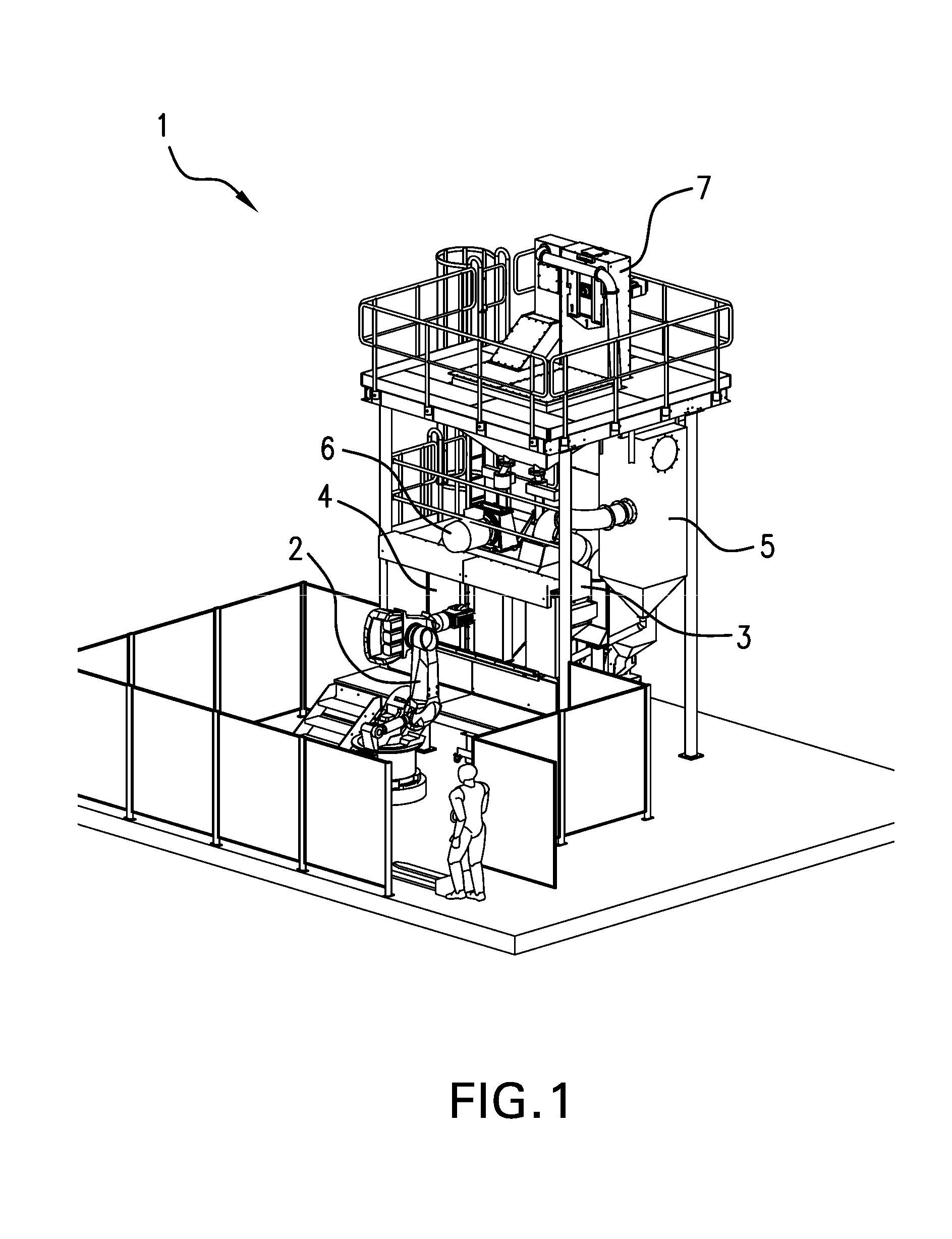
[0017]FIG. 1 illustrates a shot-blasting installation 1 for blasting work pieces made from light metal alloys, in particular for blasting cast work pieces made from magnesium alloys. The installation 1 comprises a loading and unloading robot 2, a blasting chamber 3 and a sliding door 4 which is used as access to the actual blasting chamber 3, a manifold 5 for all the pipelines of the blasting installation which carry air and blasting agent, at least two blasting wheels 6 and a bucket conveyor 7 which is used to return the blasting agent to the blasting wheels 6. As can be seen from FIG. 1, the complete blasting installation 1 extends over several storeys.

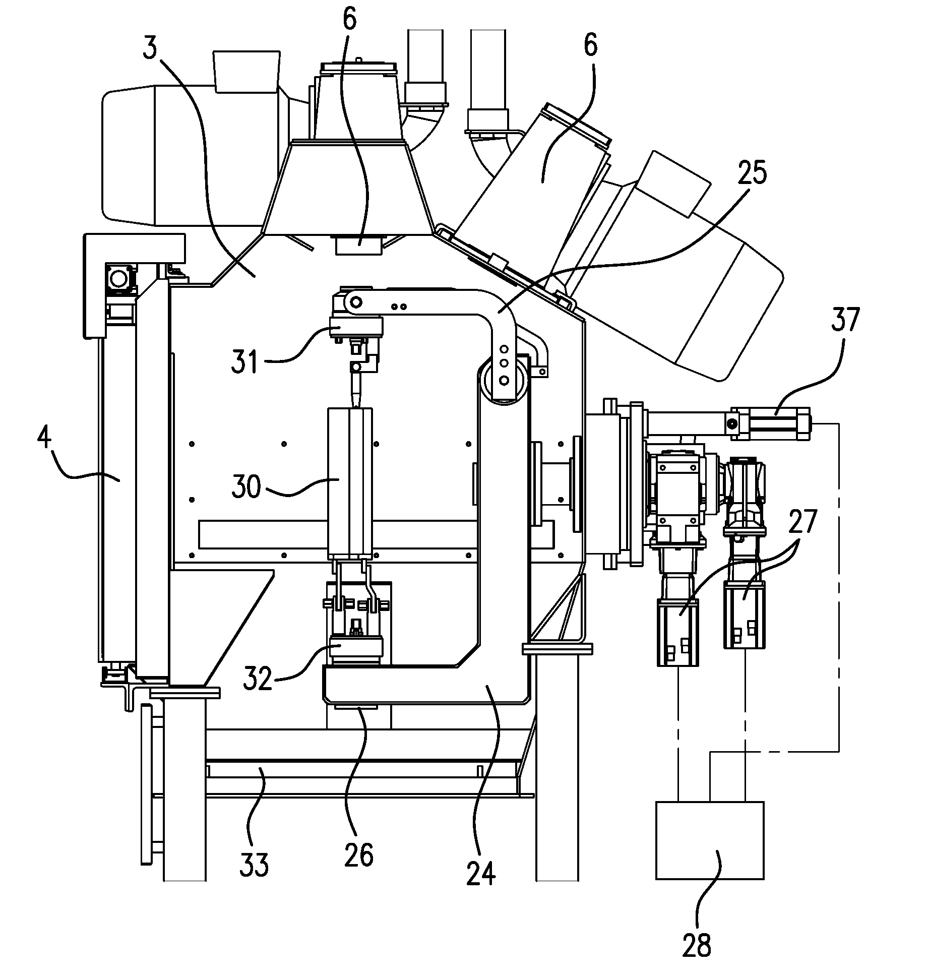
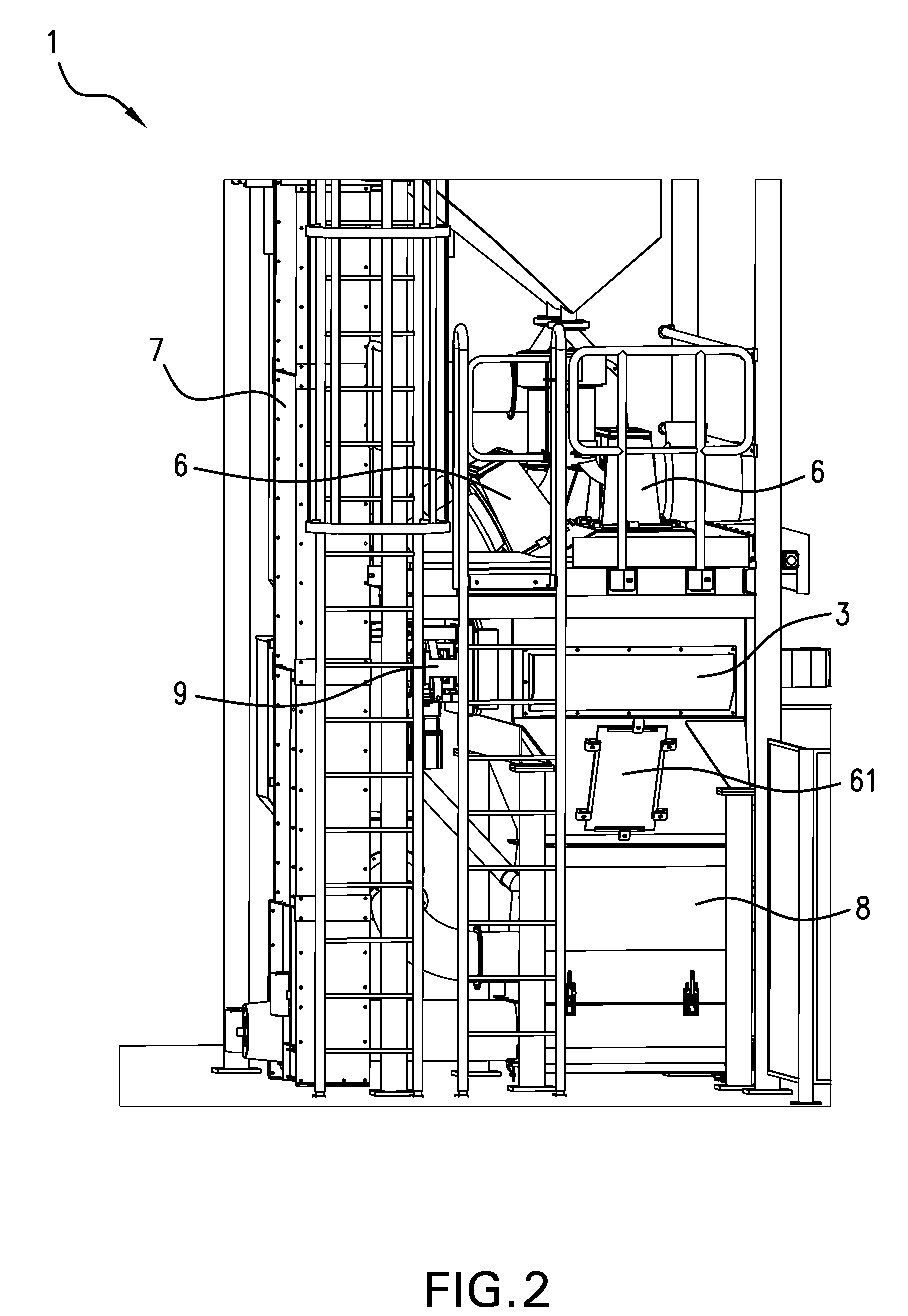
[0018]FIGS. 2 and 3 provide a detailed illustration of the same blasting installation 1 as that shown in FIG. 1. FIG. 2 illustrates a side view of the blasting installation 1. As well as the bucket conveyor 7 and the blasting wheels 6, FIG. 2 also clearly reveals how a separator 8 is arranged directly beneath the blasting chamber 3....


PUM

PropertyMeasurementUnit
angleaaaaaaaaaa
movementsaaaaaaaaaa
widthaaaaaaaaaa

Abstract

A shot-blasting installation (1) for blasting work pieces (30) made from light metal alloys, comprising at least one blasting chamber (3) for receiving the work pieces that are to be blasted, at least two blasting wheels (6) arranged in walls of the blasting chamber for introducing a blasting agent into the blasting chamber, and a separator (8) for separating the mixture of blasting agent and material that has been removed by blasting, wherein the separator (8) is arranged directly beneath the blasting chamber (3), and wherein a manipulator (10) for handling the cast work piece (30) during blasting is arranged in the blasting chamber (3).

Description

BACKGROUND OF THE INVENTION[0001]The invention relates to a shot-blasting installation for blasting work pieces made from light metal alloys, comprising at least one blasting chamber for receiving the work pieces that are to be blasted, at least two blasting wheels arranged in walls of the blasting chamber for introducing a blasting agent into the blasting chamber, and a separator for separating the mixture of blasting agent and material that has been removed by blasting.[0002]To enable as much weight as possible to be saved, cast work pieces made from light metal alloys, in particular made from aluminium and magnesium alloys, are increasingly being used in motor vehicle construction. The work pieces, which are produced by die-casting or sand-casting processes, have to be deburred and cleaned after casting. After the casting operation, the work pieces often have an uneven and irregular outer surface. To improve the appearance of the work pieces, the outer surfaces have to be ground,...

Claims


Application Information

Patent Timeline
Patent Type & Authority Patents(United States)
IPC IPC(8): B23C3/18B24C1/10
CPCB24C3/14B24C9/006B24C3/18Y10T29/479Y02P70/10G01M3/086F16K37/0058
Inventor INDLEKOFER, MARKUS
Owner DISA IND
Why Eureka
Try Eureka