Method of using ultrasound to inspect a part in immersion

a technology of immersion and ultrasound, applied in the direction of instruments, specific gravity measurement, magnetic property measurement, etc., can solve the problem that the lateral dead zone cannot be eliminated

Active Publication Date: 2008-09-09
SN DETUDE & DE CONSTR DE MOTEURS DAVIATION S N E C M A
View PDF6 Cites 0 Cited by
  • Summary
  • Abstract
  • Description
  • Claims
  • Application Information

AI Technical Summary

Benefits of technology

[0009]A particular object of the invention is to use ultrasound to inspect an immersed part by eliminating the lateral shadow zones, where such inspection is simple, effective, and inexpensive.
[0010]To this end, the invention provides a method of using ultrasound to inspect a part in immersion, the method making use of a transducer emitting a focused ultrasound wave beam and picking up the echoes produced by the focused beam being reflected on any defects in said part, the axis of the emitted focused beam being perpendicular to the surface of the part, the method consisting in using a multi-element annular ultrasound transducer associated with electronic focusing means, and when the axis of the focused beam is close to an edge of the part and is passing into a corresponding shadow zone that might mask a defect present in said zone, at least to some extent, in tilting the axis of the focused beam towards the edge of the part relative to the normal to the surface of the part, by an angle that is small enough to avoid modifying the amplitude of the wave reflected by the defect, and large enough to eliminate the lateral shadow zone over all or substantially all of the depth of the part.
[0011]The method of the invention makes it possible to detect a defect close to an edge of the part and situated in a lateral shadow zone, in the same manner as for a defect lying outside the shadow zone. The signal reflected by the defect is returned towards the transducer in the direction of incidence, such that the amplitude of the echo picked up by the transducer is substantially equal to the amplitude of the echo that would be reflected by an identical defect present at the same depth, but outside the shadow zone and detected by a beam emitted by the transducer perpendicularly to the surface of the part. It is thus possible to inspect the entire volume of the part in accurate manner.
[0015]The method also consists in determining beforehand the extent of the shadow zone from the edge of the part, thus making it possible to inspect a major fraction of said part with a focused ultrasound beam that is oriented perpendicularly to the surface of the part, and to tilt the focused beam only on penetrating into the shadow zone.

Problems solved by technology

The prior art technique does not enable this lateral dead zone to be eliminated over the full depth of the part, and, by precaution, it is necessary to give it some over-dimensioned potential value, e.g. 12 millimeters (mm), even though it is in fact smaller than that, e.g. half as wide, and that corresponds to a relatively large loss of material.

Method used


Image

  • Method of using ultrasound to inspect a part in immersion
  • Method of using ultrasound to inspect a part in immersion
  • Method of using ultrasound to inspect a part in immersion

Examples


Embodiment Construction

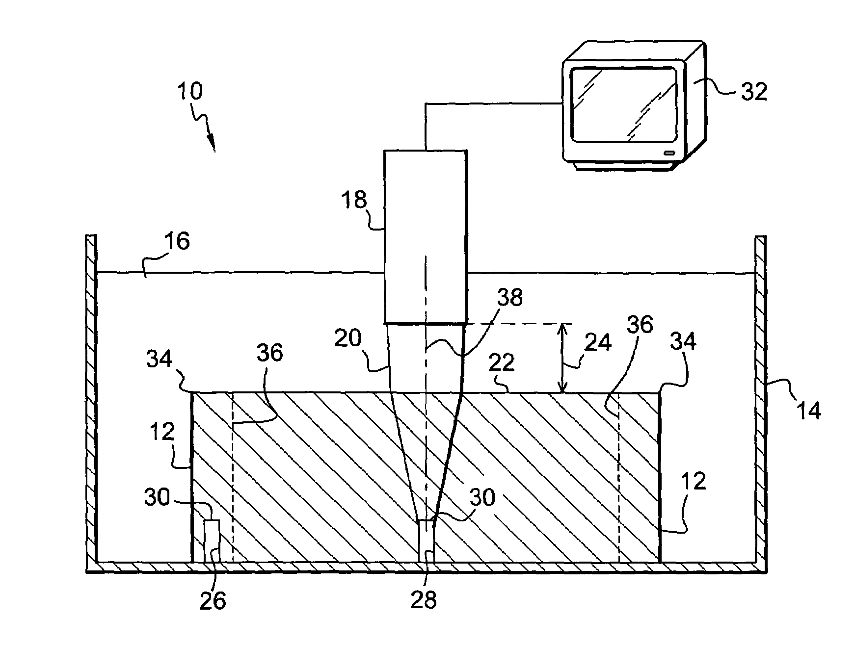
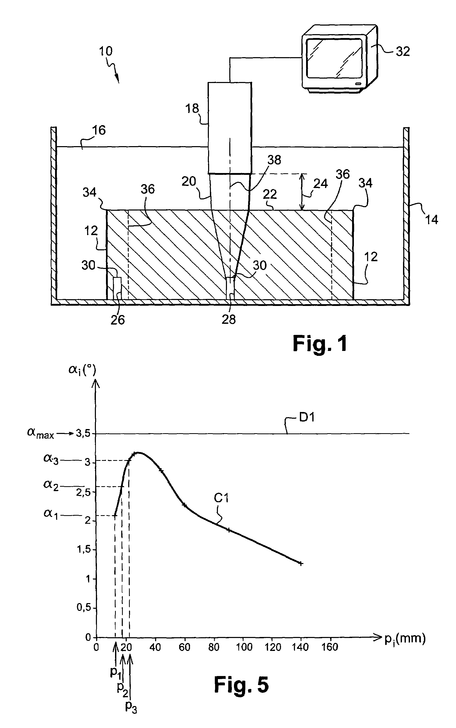
[0022]FIG. 1 is a diagram of a device 10 for ultrasound inspection of an immersed part 12, the device comprising a vessel 14 filled with water 16 in which the part 12 for inspection is immersed together with an ultrasound transducer 18 generating a focused beam 20 of ultrasound waves oriented perpendicularly to a surface 22 of the part 12, the transducer 18 being separated from said surface 22 of the part by a depth of water referred to as the “water column”24.

[0023]The transducer 18 is a multi-element ultrasound transducer associated with electronic focusing means and connected to control means, such as a microcomputer.

[0024]Some of the emitted ultrasound waves are reflected at the surface 22 of the part while the remainder are transmitted into the inside of the part, the ultrasound waves that are transmitted inside the part 12 possibly encountering a defect capable of reflecting them along their path. By way of example, a defect might be a bubble, an inclusion, etc., and is repres...


PUM

PropertyMeasurementUnit
angle of inclinationaaaaaaaaaa
diameteraaaaaaaaaa
depthaaaaaaaaaa

Abstract

A method of inspecting a part in immersion using a focused beam of ultrasound waves oriented perpendicularly to the surface of the part, the method including, when the axis of the focused beam is close to an edge of the part, tilting the axis towards the edge relative to the normal to the surface of the part in order to eliminate the lateral shadow zone over all or substantially all of the depth of the part.

Description

[0001]The present invention relates to a method of inspecting a part in immersion by means of a focused ultrasound wave beam in order to detect defects in the part such as, for example, bubbles, inclusions, etc.BACKGROUND OF THE INVENTION[0002]This technique is implemented in a vessel filled with an acoustic coupling liquid such as water, using an ultrasound transducer that is immersed in the water and that is pointed towards the part to be inspected perpendicularly to a surface thereof, the transducer being separated from the surface of the part by a depth of water referred to as the “water column”.[0003]The transducer emits a focused beam of ultrasound waves, some of which are reflected at the surface of the part, while the remainder are transmitted to the inside of the part, the transmitted ultrasound waves possibly encountering an internal defect capable of reflecting them on their path within the part. The echoes coming from these reflections are picked up by the transducer, an...

Claims


Application Information

Patent Timeline
Patent Type & Authority Patents(United States)
IPC IPC(8): G01N29/06G01N29/26G01N29/30
CPCG01N29/043G01N29/11G01N29/221G01N29/225G01N29/265G01N2291/106G01N2291/015G01N2291/044G01N2291/101
Inventor CHATELLIER, JEAN-YVES FRANCOIS ROGERCOULETTE, RICHARD MICHAEL
Owner SN DETUDE & DE CONSTR DE MOTEURS DAVIATION S N E C M A
Why Eureka
Try Eureka