Gas "true" convection bake oven

a convection oven and gas technology, applied in the field of gas “true” convection ovens, can solve the problems of loss of heat from the heat source, uneven heating of food in the oven, and only as hot air being blown through the fan,

Inactive Publication Date: 2008-09-09
DYNAMIC COOKING SYST
View PDF22 Cites 31 Cited by
  • Summary
  • Abstract
  • Description
  • Claims
  • Application Information

AI Technical Summary

Problems solved by technology

This arrangement has the disadvantage that the air being blown through the fan is only as hot as the air within the oven cavity.
Thus the heating of the food in the oven is uneven and much of the heat from the heat source is lost.
This has the result of significantly increasing the cost of the oven due to the fact that the oven must be adapted to operate multiple heat sources of various type and size.
Additionally, it is difficult to install a gas burner in close proximity to the fan, as the turbulence caused by the fan will greatly affect flame stability and emission.
It has also been difficult to design a gas burner which can function in both fan-on and fan-off conditions.

Method used


Image

  • Gas "true" convection bake oven
  • Gas "true" convection bake oven
  • Gas "true" convection bake oven

Examples


Embodiment Construction

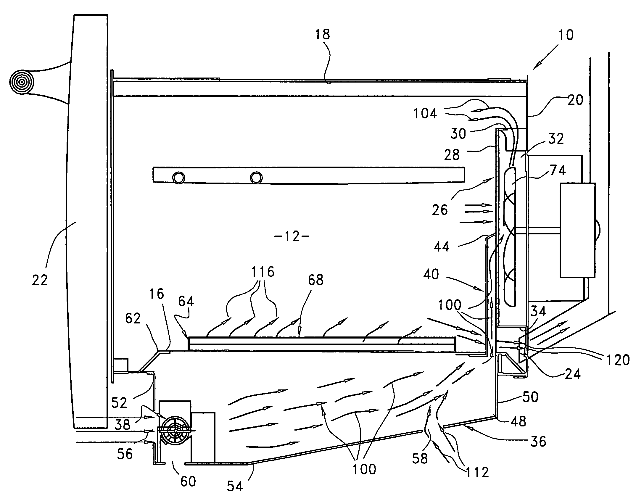
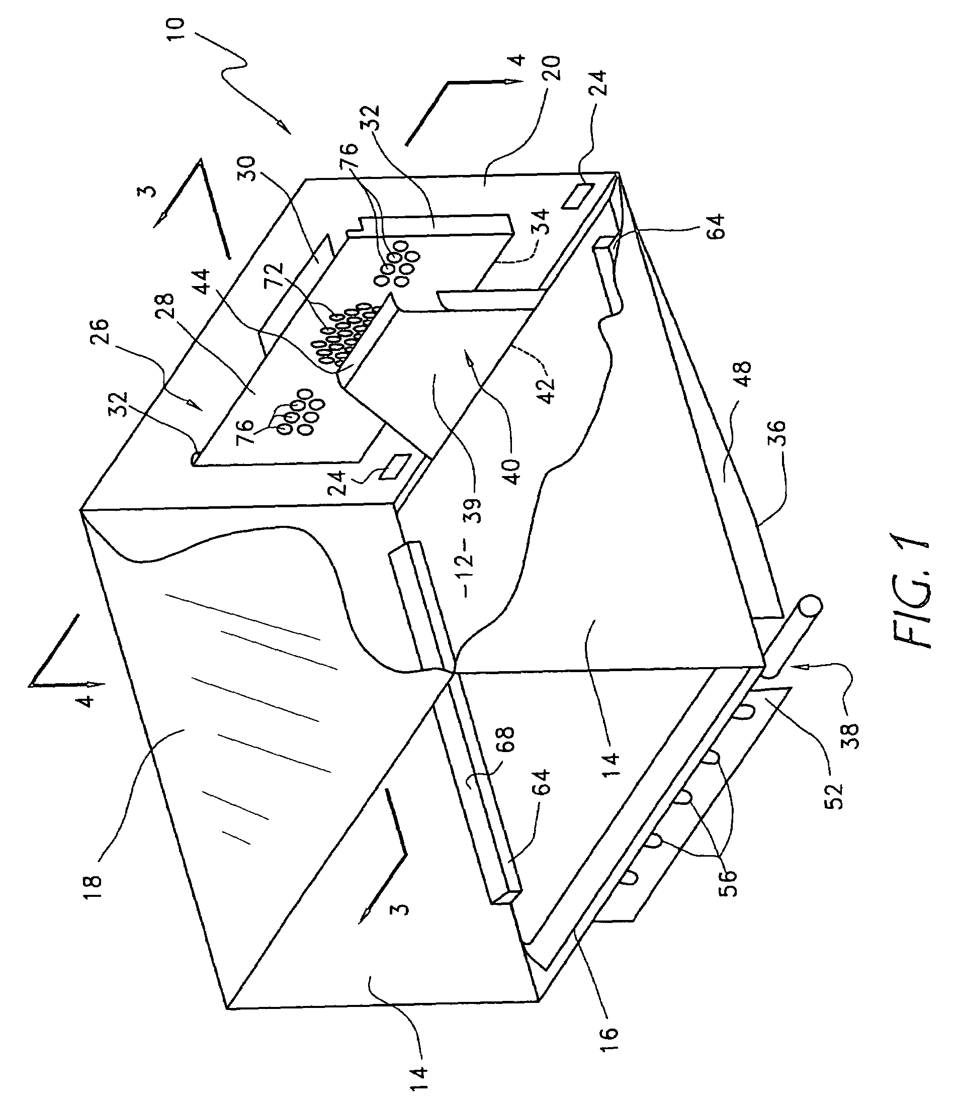
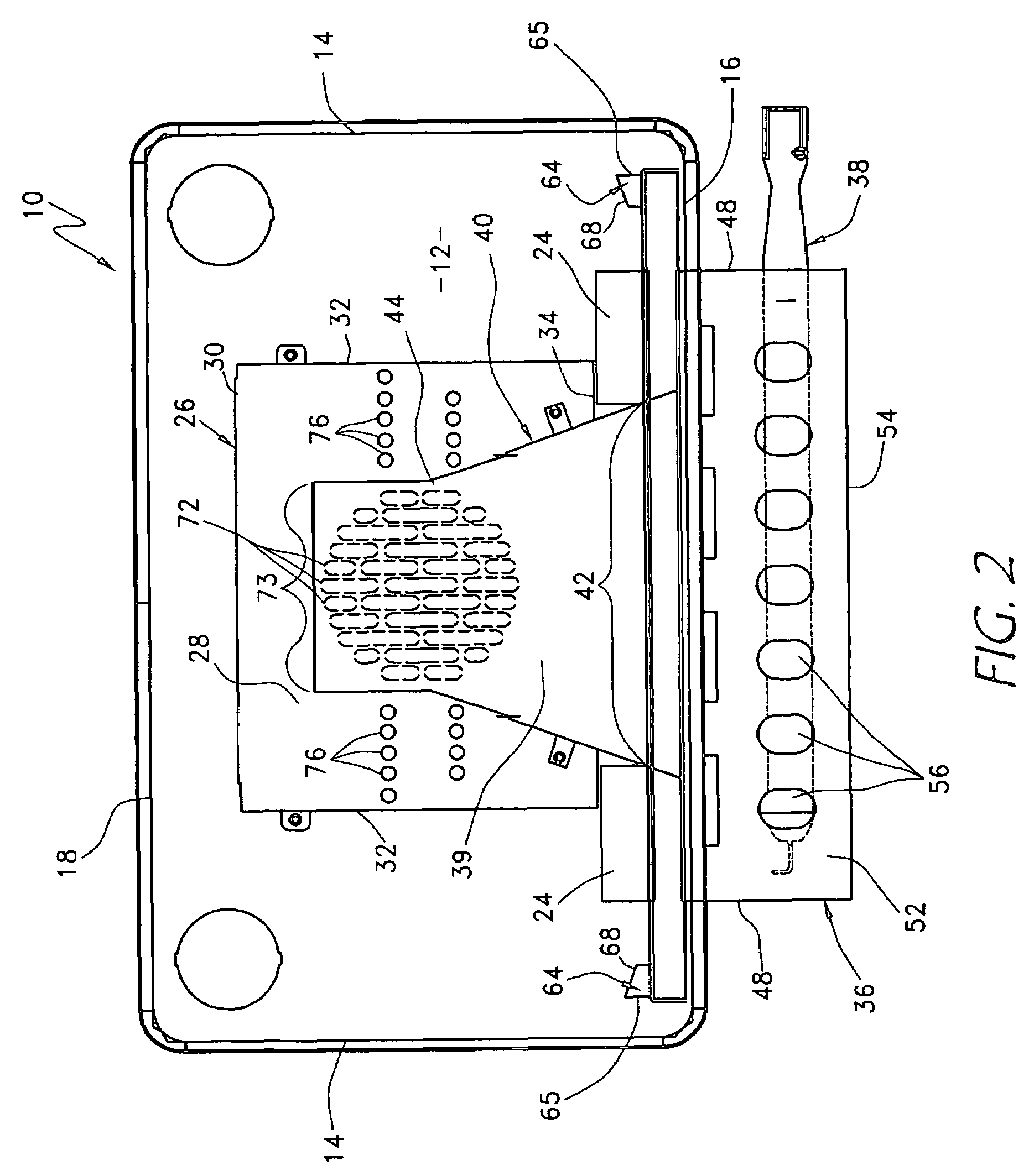
[0026]A gas ‘true’ convection bake oven having preferred features and advantages is shown in FIGS. 1-4. Specifically, an oven 10 is shown comprising an oven cavity 12 defined by two upright side walls 14, a bottom wall 16, a top wall 18, a back wall 20, and a door 22. The back wall 20 of the oven 10 preferably includes one or more exhaust vents 24. At the rear of the oven cavity 12 and adjacent the back wall 20, is preferably a fan compartment 26 defined by a baffle plate 28, and top 30, side 32, and bottom 34 flanges. A combustion box 36 is disposed below the oven bottom wall 16, and includes a gas burner 38. Disposed between the baffle plate 28 and the oven cavity 12 is preferably a flue spout 40. The lower end 42 of the flue spout 40 is in fluid communication with the combustion box 36, and the upper end 44 of the flue spout 40 preferably covers a portion of the baffle plate 28. The open space within the oven cavity provides a cooking space into which can be placed a food product...


PUM


Abstract

Disclosed is a convection oven capable of producing a “true” convection cooking environment with a single gas burner disposed underneath the oven bottom in a combustion box. A fan compartment is disposed substantially at the center of the back wall, and defined by a baffle plate with a central fan inlet, a plurality of rearward-extending flanges, and a portion of the oven back wall. A centrifugal fan is disposed within the fan compartment. A flue spout is disposed between the oven cavity and the fan compartment and is adapted to join the combustion box and the oven cavity in fluid communication. Thus the centrifugal fan, located substantially centrally within the fan compartment will draw hot air and flue products upward from the combustion box, through the flue spout, through the central fan inlet, and blow the hot air and flue products into the oven cavity through peripheral fan outlets formed in the fan compartment. The oven may alternatively be operated in a fan-off mode, thus allowing the oven cavity to be heated by the upward flow of air due to natural convection.

Description

CROSS REFERENCE TO RELATED APPLICATIONS[0001]This is a continuation of U.S. patent application Ser. No. 10 / 060,966, filed Jan. 29, 2002, now U.S. Pat. No. 6,718,965, which is incorporated herein by reference in its entirety.BACKGROUND[0002]1. Field of the Invention[0003]The invention relates in general to the field of food preparation ovens, and specifically to a gas “true” convection oven.[0004]2. Description of the Related Art[0005]Convection ovens have long been popular in the cooking industry for both residential and commercial use. Typically, a gas convection oven involves a heat source disposed underneath the oven cavity, and a fan within the cooking cavity to circulate the hot air in the cooking cavity. This arrangement has the disadvantage that the air being blown through the fan is only as hot as the air within the oven cavity. Thus the heating of the food in the oven is uneven and much of the heat from the heat source is lost.[0006]In order to improve the heating efficienc...

Claims


Application Information

Patent Timeline
Patent Type & Authority Patents(United States)
IPC IPC(8): F24C15/32A21B1/00
CPCF24C15/322
Inventor RUMMEL, RANDY L.DENG, ERIC H. Y.
Owner DYNAMIC COOKING SYST
Why Eureka
Try Eureka