Inlet guide vane control device of gas turbine

a control device and gas turbine technology, applied in the direction of machines/engines, mechanical equipment, engine starters, etc., can solve the problems of damage to or breakage of compressors, damage to or breakage of exhaust ducts, etc., to increase the operation rate, reduce the possibility, and increase the operation rate

Active Publication Date: 2008-09-09
MITSUBISHI HEAVY IND LTD
View PDF6 Cites 33 Cited by
  • Summary
  • Abstract
  • Description
  • Claims
  • Application Information

AI Technical Summary

Benefits of technology

[0017]wherein an inlet guide vane opening command is set based on a first inlet guide vane opening set by first inlet guide vane opening setting means such that a temperature of an exhaust gas discharged from the gas turbine body does not exceed a limit value, a second inlet guide vane opening set by second inlet guide vane opening setting means such that a pressure ratio of the compressor does not exceed a surge pressure ratio of the compressor, and a third inlet guide vane opening set by third inlet guide vane opening setting means such that a pressure of the exhaust gas discharged from the gas turbine body does not exceed a limit value.
[0021]According to the inlet guide vane control device of a gas turbine, as the first aspect of the present invention, the inlet guide vane opening command is set based on the first inlet guide vane opening set by the first inlet guide vane opening setting means such that the temperature of the exhaust gas discharged from the gas turbine body does not exceed the limit value, the second inlet guide vane opening set by the second inlet guide vane opening setting means such that the pressure ratio of the compressor does not exceed the surge pressure ratio of the compressor, and the third inlet guide vane opening set by the third inlet guide vane opening setting means such that the pressure of the exhaust gas discharged from the gas turbine body does not exceed the limit value. Thus, inlet guide vane opening control can be effected, with the exhaust gas temperature, the pressure ratio of the compressor, and the exhaust gas pressure being taken into consideration. Thus, the continued operation of the gas turbine (increased rate of operation) can be ensured, with the possibility being diminished that the protective function, such as emergency shutdown, is performed.
[0022]According to the inlet guide vane control device of a gas turbine, as the second aspect of the present invention, the value of the first inlet guide vane opening or the value of the second inlet guide vane opening, whichever is higher, is selected, the selected higher value or the value of the third inlet guide vane opening, whichever is lower, is selected, and the selected lower value is set as the inlet guide vane opening command. By so doing, inlet guide vane opening control with priority placed on the avoidance of a gas turbine back pressure rise can be effected. Hence, the emergency shutdown of the gas turbine due to an exhaust gas pressure rise (gas turbine back pressure rise) can be prevented more reliably to ensure the continued operation of the gas turbine (increased rate of operation).
[0023]According to the inlet guide vane control device of a gas turbine, as the third aspect of the present invention, the value of the first inlet guide vane opening or the value of the third inlet guide vane opening, whichever is lower, is selected, the selected lower value or the value of the second inlet guide vane opening, whichever is higher, is selected, and the selected higher value is set as the inlet guide vane opening command. By so doing, inlet guide vane opening control with priority placed on the avoidance of compressor surge can be effected. Hence, compressor surge can be avoided more reliably.

Problems solved by technology

If the exhaust gas temperature or the exhaust gas pressure (gas turbine back pressure) become too high, damage to or breakage of an exhaust duct may be induced.
If the pressure ratio becomes too high, surging may occur, causing damage to or breakage of the compressor.

Method used


Image

  • Inlet guide vane control device of gas turbine
  • Inlet guide vane control device of gas turbine
  • Inlet guide vane control device of gas turbine

Examples


embodiment 1

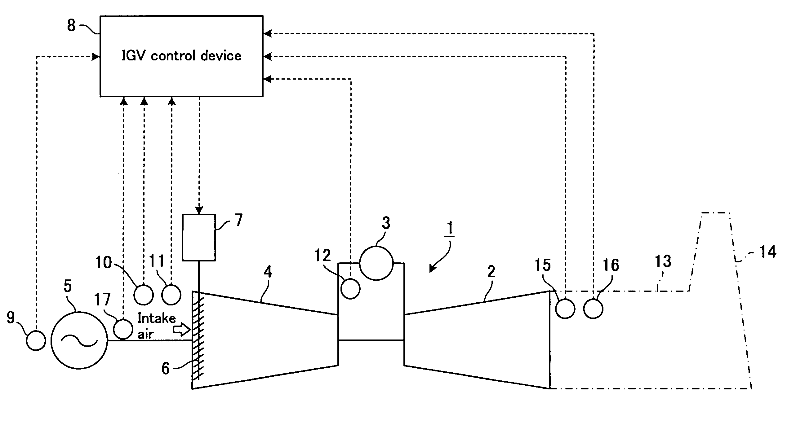
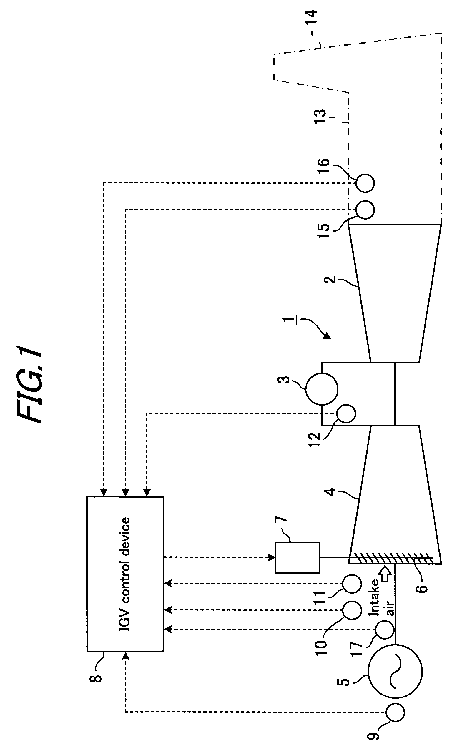
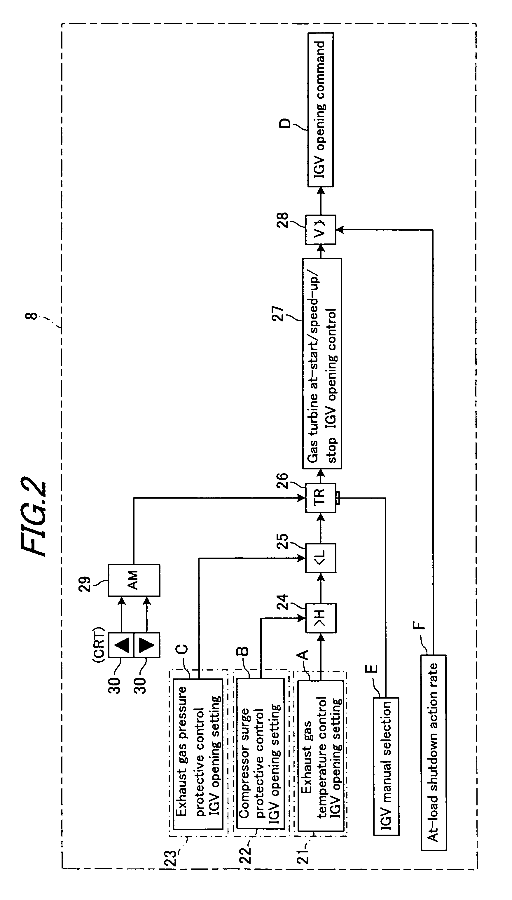
[0043]FIG. 1 is an outline view of an IGV control device of a gas turbine according to Embodiment 1 of the present invention, and the gas turbine. FIG. 2 is a block diagram showing the entire configuration of the above IGV control device. FIG. 3 is a block diagram showing the configuration of an exhaust gas temperature control section in the above IGV control device. FIG. 4 is a block diagram showing the configuration of a compressor surge protective control section in the above IGV control device. FIG. 5 is a block diagram showing the configuration of an exhaust gas pressure protective control section in the above IGV control device.

[0044]FIG. 6 is a view showing the relationship between the intake air amount of a compressor and the exhaust gas temperature. FIG. 7 is a view showing the relationship between the pressure ratio of the compressor and the exhaust gas temperature. FIG. 8 is a view showing examples of an IGV opening schedule concerned with exhaust gas temperature control....

embodiment 2

[0085]FIG. 15 is a block diagram showing the entire configuration of an IGV control device of a gas turbine according to Embodiment 2 of the present invention. In FIG. 15, the same portions as those in FIG. 2 are assigned the same numerals and symbols as those in FIG. 2. The IGV control device 8 of a gas turbine according to the aforementioned Embodiment 1 is in the “gas turbine back pressure rise avoidance priority mode”. On the other hand, an IGV control device 78 of a gas turbine according to the present Embodiment 2 is in a “compressor surge avoidance priority mode”. This feature will be described hereinbelow, but other features are the same as those in the aforementioned Embodiment 1, and their explanations will be omitted herein (see FIGS. 1 to 5).

[0086]As shown in FIG. 15, the IGV control device 78 of the present Embodiment 2 has an exhaust gas temperature control section 21 as a first inlet guide vane opening setting means, a compressor surge protective control section 22 as...

embodiment 3

[0091]FIG. 16 is a block diagram showing the entire configuration of an IGV control device of a gas turbine according to Embodiment 3 of the present invention. In FIG. 16, the same portions as those in FIGS. 2 and 15 are assigned the same numerals and symbols as those in FIGS. 2 and 15. The IGV control device 8 of a gas turbine according to the aforementioned Embodiment 1 is in the “gas turbine back pressure rise avoidance priority mode”. The IGV control device 78 of a gas turbine according to the aforementioned Embodiment 2 is in the “compressor surge avoidance priority mode”. On the other hand, an IGV control device 88 of a gas turbine according to the present Embodiment 3 is configured to switch between the “gas turbine back pressure rise avoidance priority mode” and the “compressor surge avoidance priority mode”. This feature will be described hereinbelow, but other features are the same as those in the aforementioned Embodiments 1 and 2, and their explanations will be omitted h...


PUM


Abstract

An IGV opening command is set based on an IGV opening A set by an exhaust gas temperature control section, an IGV opening B set by a compressor surge protective control section, and an IGV opening C set by an exhaust gas pressure protective control section. The value of the IGV opening A, or the value of the IGV opening B, whichever is higher, is selected, the higher selected value, or the value of the IGV opening C, whichever is lower, is selected, and the lower selected value is set as the IGV opening command (gas turbine back pressure rise avoidance priority mode). Alternatively, the value of the IGV opening A, or the value of the IGV opening C, whichever is lower, is selected, the lower selected value, or the value of the IGV opening B, whichever is higher, is selected, and the higher selected value is set as the IGV opening command (compressor surge avoidance priority mode). Alternatively, a switcher switches between these modes.

Description

BACKGROUND OF THE INVENTION [0001]1. Field of the Invention[0002]This invention relates to an inlet guide vane control device of a gas turbine comprising a gas turbine body, a combustor, and a compressor with an inlet guide vane.[0003]2. Description of the Related Art[0004]A gas turbine, which comprises a gas turbine body, a combustor, and a compressor with an inlet guide vane (IGV), is equipped with various control devices and protective devices, such as an IGV control device for exercising opening control of IGV, and a fuel control device for controlling the amount of fuel supply to the combustor.[0005]A conventional IGV control device determined an IGV opening command based on a gas turbine output corrected with the intake air temperature of the compressor (the temperature of the air flowing into the compressor) (corrected gas turbine output: the product of a correction factor, set as a function of the intake air temperature, and gas turbine output), and effected the opening cont...

Claims


Application Information

Patent Timeline
Patent Type & Authority Patents(United States)
IPC IPC(8): F04D15/00
CPCF02C9/20F04D27/0246F05D2270/0831F05D2270/112F05D2270/301F05D2270/3011F05D2270/3013F05D2270/303F05D2270/304
Inventor FUJII, KENTAROTOYAMA, KOZO
Owner MITSUBISHI HEAVY IND LTD
Why Eureka
Try Eureka