Method of detecting vehicle-operator state

a technology of operator state and vehicle, which is applied in the field of vehicle operator state detection, can solve the problems of largely ignored, system limitation to eye gaze, and known vehicle accidents, and achieve the effects of improving response times, fewer components, and high accuracy

Active Publication Date: 2008-09-09
APTIV TECH LTD
View PDF30 Cites 190 Cited by
  • Summary
  • Abstract
  • Description
  • Claims
  • Application Information

AI Technical Summary

Benefits of technology

[0008]Objects features and advantages of this invention include a method of detecting driver distraction and drowsiness utilizing a low-cost and compact system having only one camera capable of utilizing associated algorithms to recognize known drivers for improved response times and categorizing new drivers. Associated confidence levels of output data are repeatable, highly accurate, and the system required to support the method is relatively inexpensive, utilizes fewer components and in service has a long and useful life.

Problems solved by technology

Vehicle accidents are known to occur when a driver becomes drowsy, distracted, or generally lacks awareness.
This system is limited to eye gaze and, unfortunately, other facial characteristics (e.g. head pose) that greatly contribute in determining driver state are essentially ignored.
Yet further, to measure direction of eye gaze the processor algorithms require at least two cameras for reliable determination, which is costly.

Method used


Image

  • Method of detecting vehicle-operator state
  • Method of detecting vehicle-operator state
  • Method of detecting vehicle-operator state

Examples


Embodiment Construction

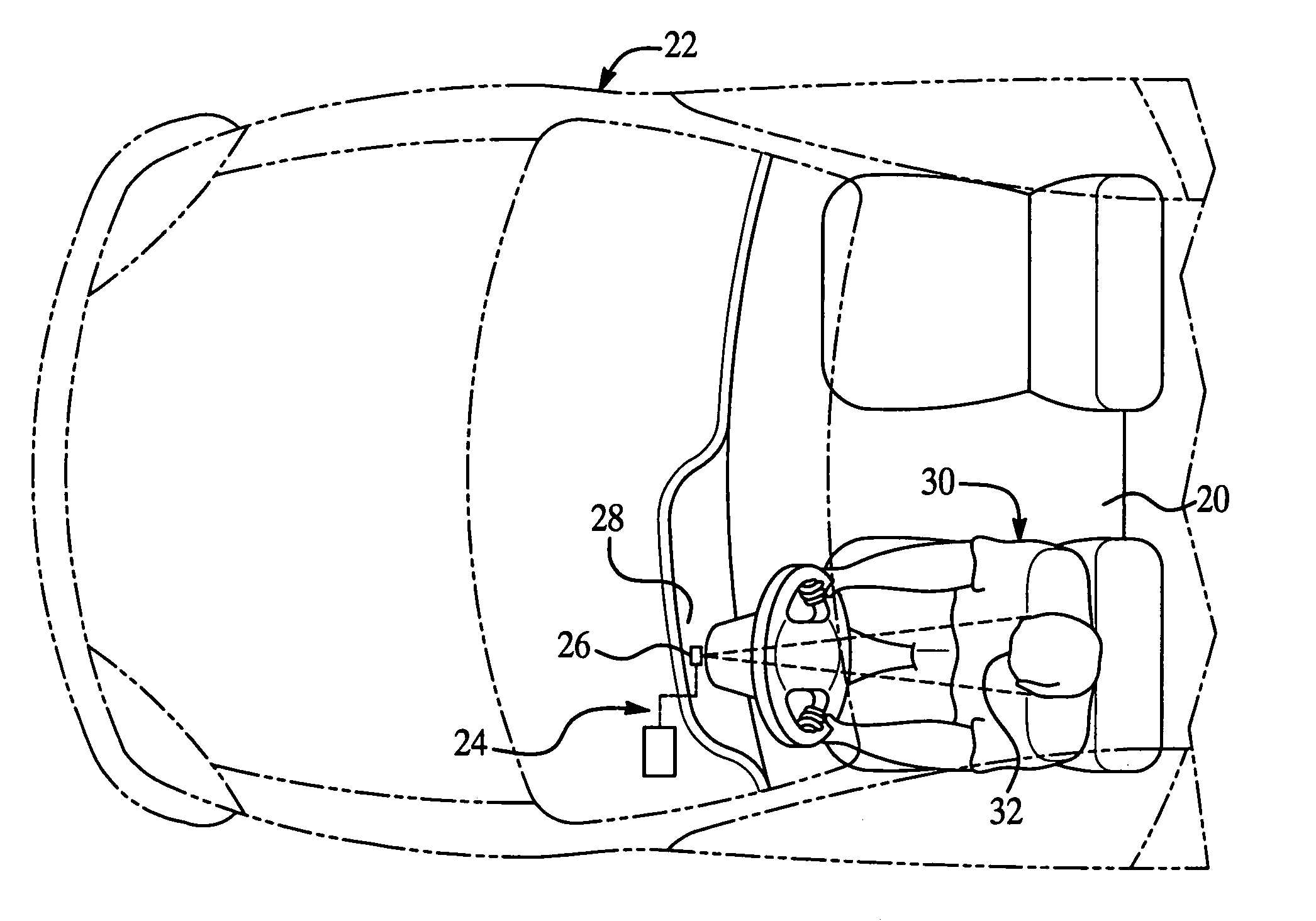
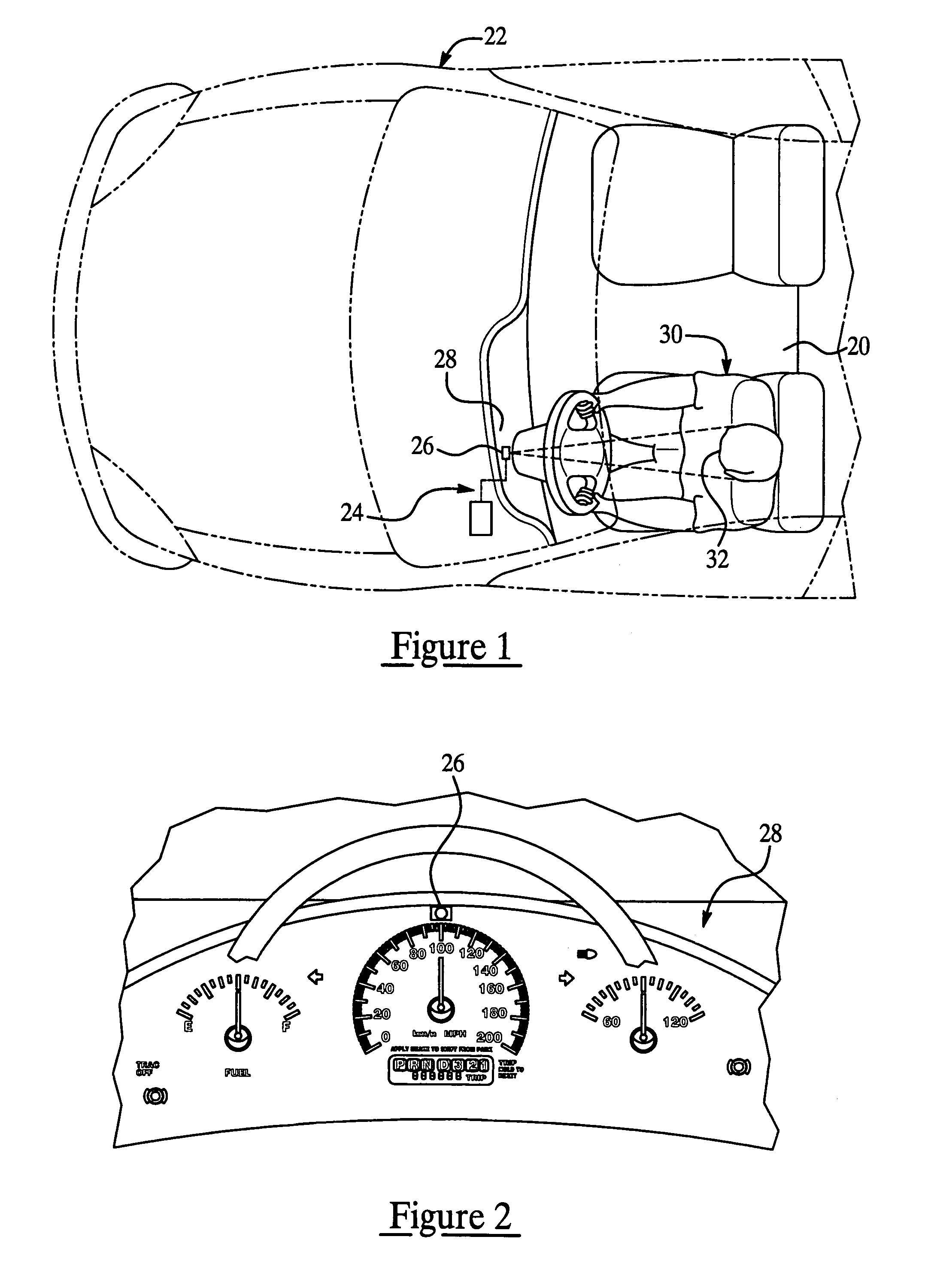
[0018]Referring to FIGS. 1 and 2, an interior or compartment 20 of a vehicle 22 is generally shown equipped with a vehicle operator state detection system 24, which applies a method of detecting vehicle-operator state. Vehicle 22 has only one imaging sensor or video camera 26 located generally within an instrument panel, dash or console 28 of the vehicle 22 and preferably focused on an operator or driver 30. The video camera 26 is shown mounted generally in a mid-region of the dash 28 in front of the driver 30. Other locations for mounting the video camera 26 are possible provided the camera 26 is capable of focusing upon three distinctive points of the operator's facial features 32 at substantially all times. For example, the video camera 26 may be mounted in the steering assembly or may be mounted generally in the instrument cluster provided symmetry of the face is preserved thus limiting mounting choice freedom generally in a vertical direction, and as disclosed in U.S. applicati...


PUM


Abstract

A method of detecting the state of an operator of a vehicle utilizes a low-cost operator state detection system having no more than one camera located preferably in the vehicle and directed toward a driver. A processor of the detection system processes preferably three points of the facial feature of the driver to calculate head pose and thus determine driver state (i.e. distracted, drowsy, etc.). The head pose is generally a three dimensional vector that includes the two angular components of yaw and pitch, but preferably not roll. Preferably, an output signal of the processor is sent to a counter measure system to alert the driver and / or accentuate vehicle safety response.

Description

TECHNICAL FIELD[0001]The present invention relates to a method of detecting vehicle-operator state and more particularly to a method utilizing a video imaging system for measuring driver distraction, target awareness, drowsiness and fatigue.BACKGROUND OF THE INVENTION[0002]Vehicle accidents are known to occur when a driver becomes drowsy, distracted, or generally lacks awareness. In an attempt to anticipate driver drowsiness and / or distraction, known video monitoring systems include one or two cameras focused on the driver of the vehicle to capture images of the driver's facial characteristics which are indicative of the driver's state. Such facial characteristics include the position, orientation, and movement of the driver's head, eye position and gaze, and ocular data. By recognizing the driver's facial characteristics, vehicle control systems can provide enhanced vehicle functions and possibly reduce the risks of driver induced accidents.[0003]For example, one such system is dis...

Claims


Application Information

Patent Timeline
Patent Type & Authority Patents(United States)
IPC IPC(8): G08B23/00
CPCG06K9/00362G08B21/06G06T7/0042G06T2207/30201G06T7/73G06V40/10
Inventor KISACANIN, BRANISLAV
Owner APTIV TECH LTD
Why Eureka
Try Eureka