
Collapsible parabolic reflector

a parabolic reflector and collapsible technology, applied in the field of collapsible parabolic reflectors, can solve the problems of cumbersome carrying, inability to bring on a normal passenger airplane, and inability to make communication equipment using parabolic reflectors portable, etc., to achieve convenient assembling and disassembly, and the effect of being sufficiently stabl

Active Publication Date: 2008-09-09
GLOBAL SKYWARE LTD
View PDF7 Cites 5 Cited by
  • Summary
  • Abstract
  • Description
  • Claims
  • Application Information

AI Technical Summary

Benefits of technology

"The invention is about a collapsible parabolic reflector for use in communication equipment. The reflector is made up of multiple sectors that are connected at a central hub. These sectors can rotate around the hub, allowing for easy collapsing and retracting of the reflector. The design is simple and stable, without the need for additional support devices or loose parts. The reflector is easy to assemble and disassemble, making it ideal for portable and independent broadband communications. The technical effect of the invention is to provide a more portable and compact parabolic reflector for improved signal amplification and concentration."

Problems solved by technology

However, it is difficult to make communication equipment using antennas with parabolic reflectors portable, because of the reflectors as such.
Often, they have sizes that make them cumbersome to carry and impossible to bring on a normal passenger airplane.
One drawback with this design is the need for a rope and a pulley to form the to parabolic shape of the reflector.
Moreover, this forming method is cumbersome to perform.
There is also a problem of attaining the correct form of the antenna, and to attain the same form every time.
The need for support means to keep the petal segments in place is a disadvantage.
Whether in the form of wire braces or thin plastic film, they interfere with the line of sight of the reflector.
They also complicate the mounting and dismounting of the reflector and make it a complex construction.
That makes them cumbersome to assemble and there is a risk that parts may be lost.

Method used


Image

  • Collapsible parabolic reflector
  • Collapsible parabolic reflector
  • Collapsible parabolic reflector

Examples


Embodiment Construction

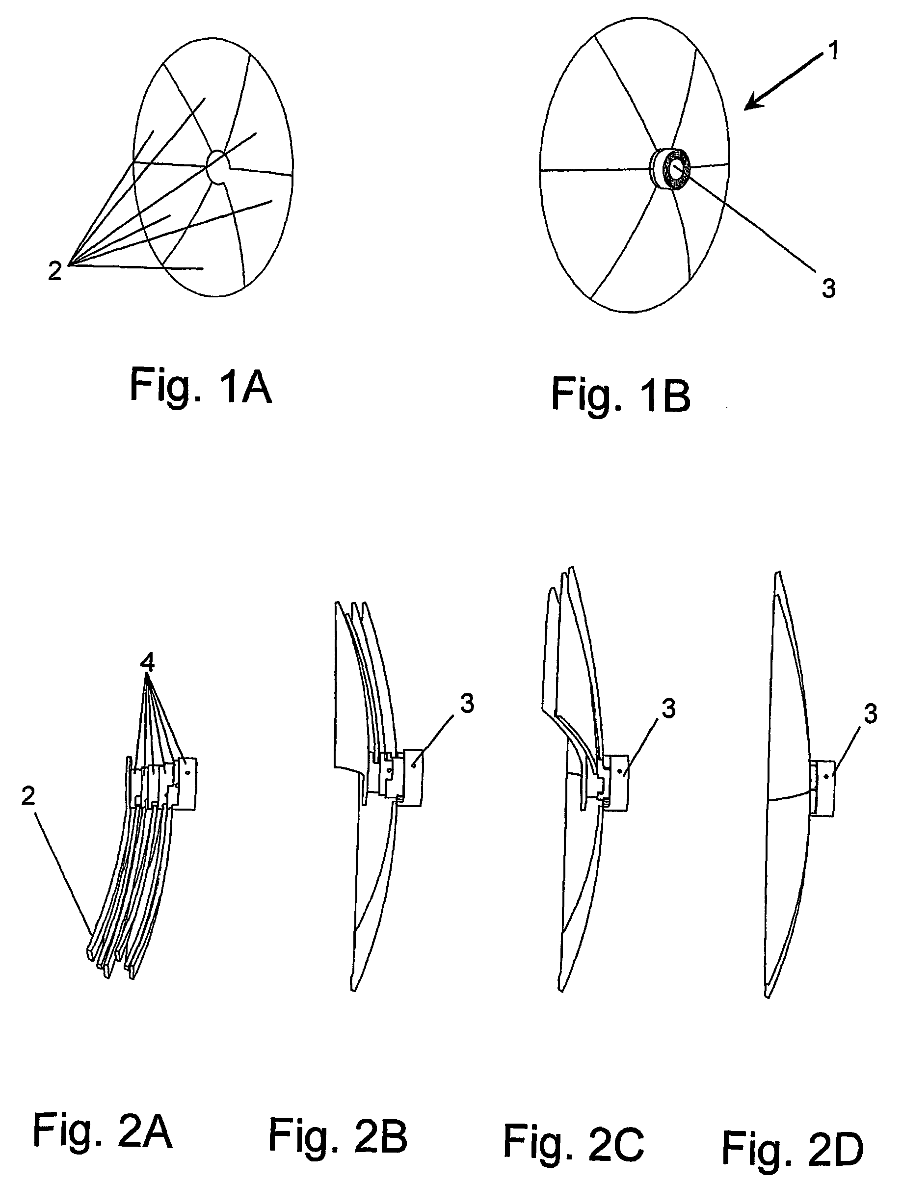
[0024]The reflector 1 shown in FIGS. 1A and 1B is divided into sectors 2, in this case four sectors, which are connected at a central hub 3. A wide range of sizes of the reflector could be anticipated, for example between 0.6 and 2.5 m in diameter. Preferably, the reflector would be about 1 m in diameter.

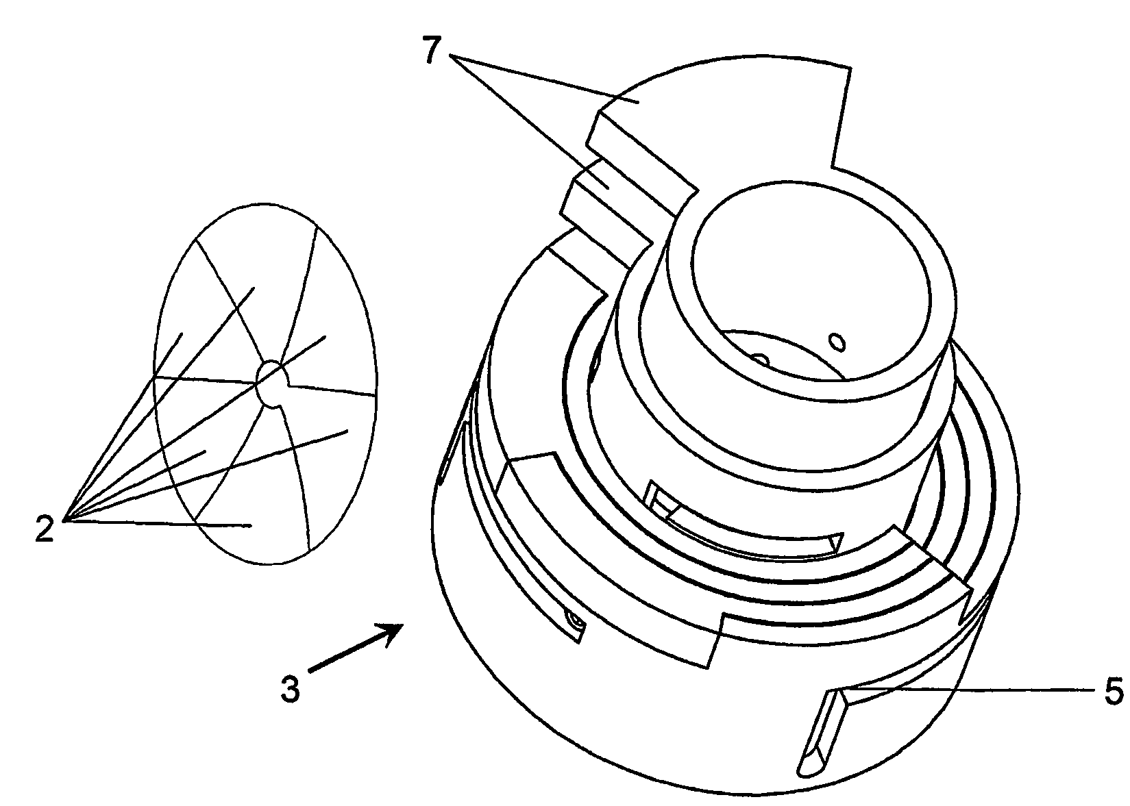
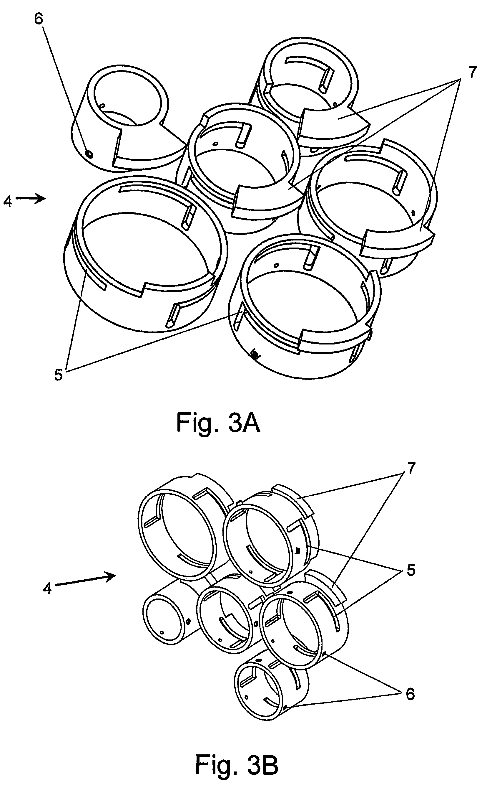
[0025]FIGS. 2A through 2D illustrate different positions of the sectors 2 during a mounting or unfolding process from a retracted position (FIG. 2A) to an extended position (FIG. 2D). In a fully extended position, as in FIG. 2D, the sectors 2 extend 360° around the hub in a seamless, edge to edge fashion. In a fully retracted position, as in FIG. 2A, the sectors 2 overlap each other, so as to form a compact unit. As can be best seen in FIG. 2A, the hub 3 is constituted by a number of hub sleeves 4, each being firmly connected to an associated sector 2. The hub sleeves 4 are concentrically arranged one radially inside the other, with consecutively decreasing radii. The sectors 2 may ...


PUM


Abstract

Parabolic reflector includes a number of sectors (2) being connected to each other at a central hub (3), the parabolic reflector being collapsible from an extended position (9), in which the sectors together extend 360 °around the hub (3), to a retracted position (8), in which the sectors (2) are brought together into a compact unit. Each sector (2) is rigid and is firmly joined to a cylindrical hub sleeve (4). The hub sleeves (4) together form the hub (3), around which the sectors (2) are journalled for limited movement around a central axis extending through the center of the hub (3). The hub sleeves (4) are concentrically arranged one radially inside the other with consecutively decreasing radii, and the hub sleeves (4) have mutually cooperating guiding surfaces that permit axial displacement of the hub so as to enable relative rotation there between.

Description

FIELD OF THE INVENTION[0001]The invention concerns a collapsible parabolic reflector of the kind comprising a number of sectors being connected to each other at a central hub, the parabolic reflector being collapsible from an extended position, in which the sectors together extend 360° around the hub, to a retracted position, in which the sectors are brought together into a compact unit. Also, the invention relates to a parabolic antenna including such a collapsible reflector.PRIOR ART[0002]In the field of communication technology over long distances, for instance between earth and a satellite, it is well known to use parabolic reflectors. They are needed for amplification and concentration of the inherently weak and directional signals of long distance communication and also for improving signal to noise ratio and thus transfer bitrates.[0003]In a world constantly demanding more flexibility and mobility there has been an increased demand for portable, independent broadband communic...

Claims


Application Information

Patent Timeline
Patent Type & Authority Patents(United States)
IPC IPC(8): H01Q15/20H01QH01Q15/16
CPCH01Q15/162H01Q15/20
Inventor SANKELA, JAN-OLOFLUNDBACK, MAGNUS
Owner GLOBAL SKYWARE LTD
Learn More