
Robot system

a robot and robot technology, applied in the field of robot systems, can solve the problems of the teaching operation can only be performed by skilled personnel in a short time, and achieve the effect of efficient carrying out the robot motion, without putting a heavy load on the operator

Inactive Publication Date: 2008-09-09
FANUC LTD
View PDF12 Cites 16 Cited by
  • Summary
  • Abstract
  • Description
  • Claims
  • Application Information

AI Technical Summary

Benefits of technology

[0009]The present invention provides a technical art capable of efficiently carrying out a robot motion, such as in a teaching operation, for moving a predetermined part of an end effector close to or separate from a predetermined part of an object, without putting a heavy load on an operator.
[0011]These fictions eliminate the need for the operator to keep the robot coordinate system in mind. With these functions, there can be for example constructed a system with which the operator can move the end effector close to a teaching position simply by depressing a key. Also when moving the end effector away from the teaching position, the operator only requires to depress a key. This makes it possible to shorten the required time for teaching operation and simplify the teaching operation. Also, the possibility of a mistaken teaching operation by which the end effector is brought in contact with the workpiece, jig, peripheral equipment, or the like can be reduced.

Problems solved by technology

As explained above, the operator needs to try and error to perform the robot teaching operation which is therefore extremely cumbersome and puts an enormous load on the operator.
Such teaching operation can only be performed by skilled personnel in a short time.

Method used


Image

  • Robot system
  • Robot system
  • Robot system

Examples


Embodiment Construction

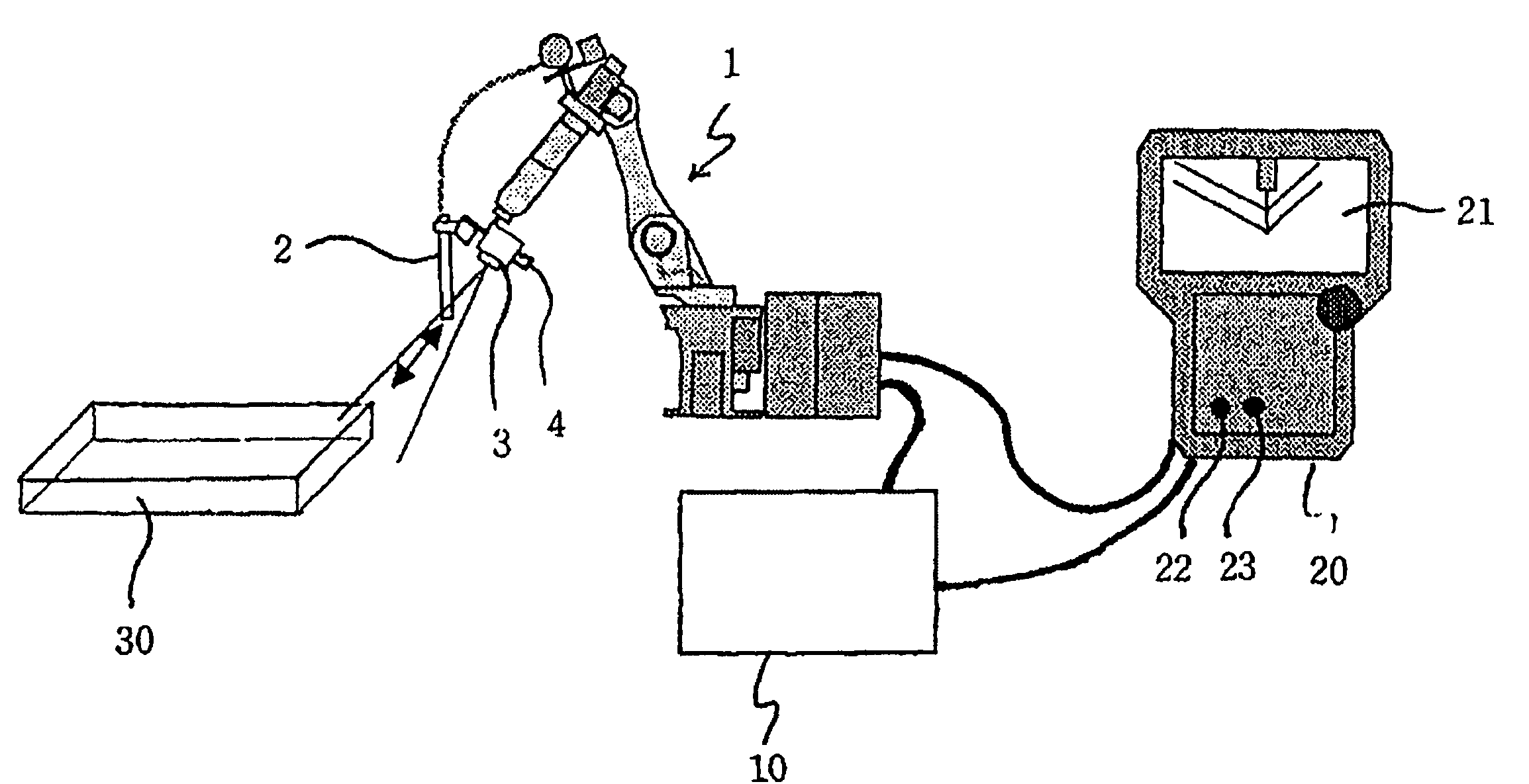
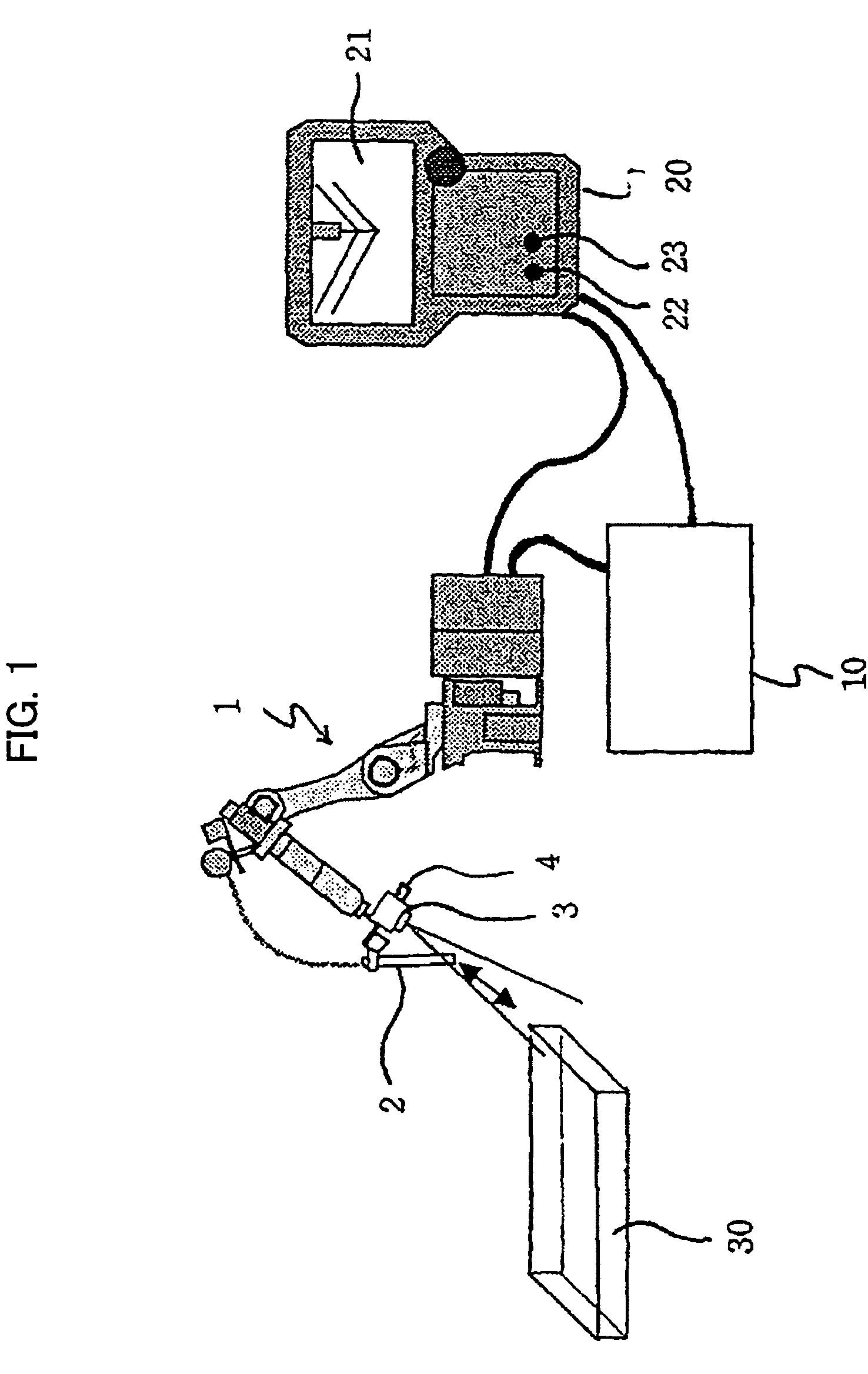
[0034]FIG. 1 shows the overall arrangement of a robot system according to one embodiment of this invention. As shown in FIG. 1, a robot's main mechanism section 1 (hereinafter referred to as robot) connected to a robot controller 10 is comprised of a 6-axis arc welding robot provided with a robot arm having a distal end thereof to which is attached an arc welding torch 2 serving as end effector. A CCD camera (CCD digital video camera, for instance) 3 serving as image capturing means of a visual sensor is attached to the vicinity (J6 flange) of the arc welding torch 2.

[0035]Mounted near the camera 3 is a distance sensor 4 that is connected to the robot controller 10. In a state where the field of view of the camera 3 is directed to an object (for instance, a component part (ditto in the following)) 30, a distance between the distance sensor 4 and the object 30 is always measured, and a distance sensor signal is supplied to the robot controller 10. Instead of the distance sensor 4, a ...


PUM


Abstract

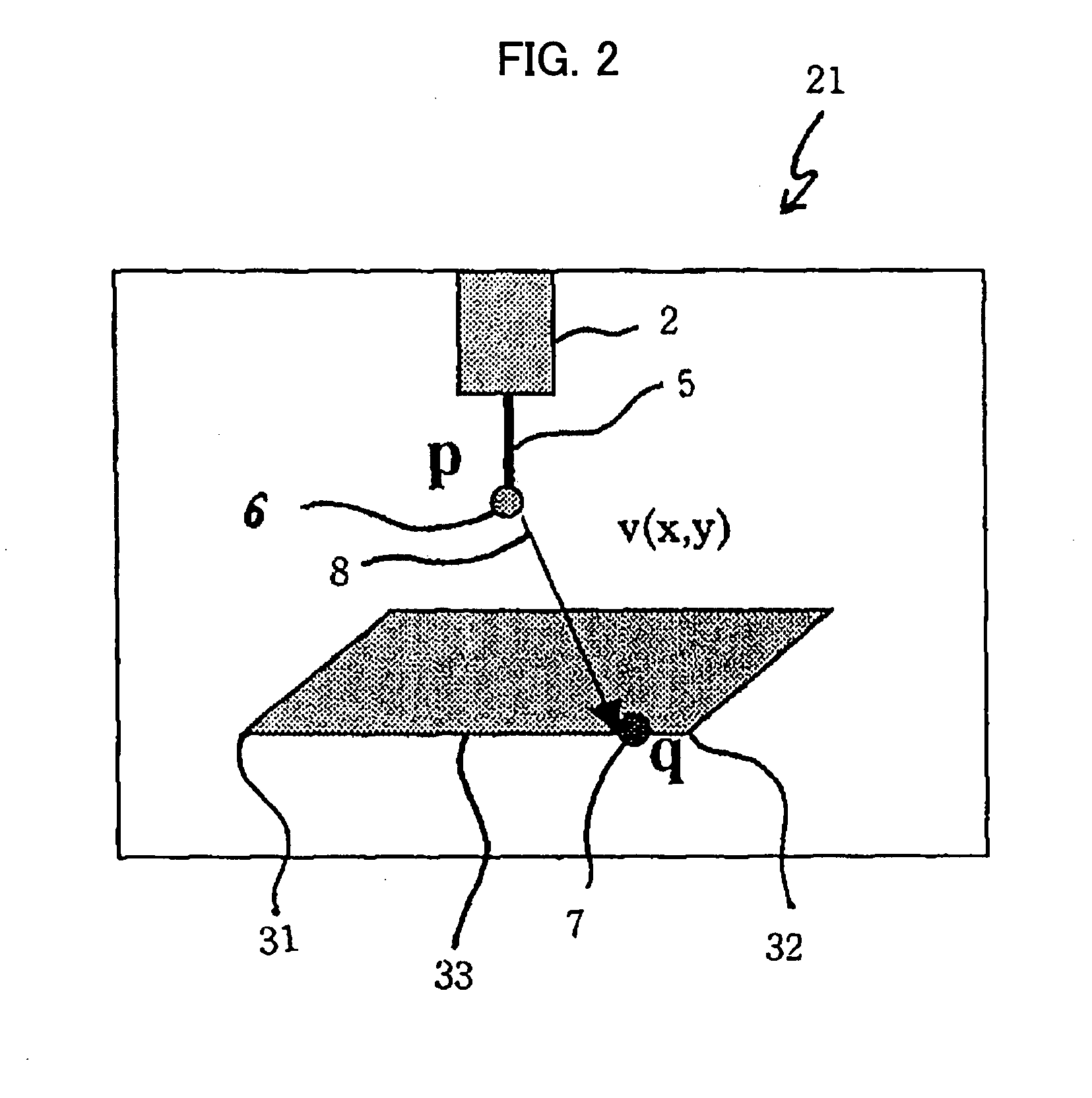
A robot system efficiently performing an operation of moving a robot to close to and / or separate from a target point, such as teaching operation. A camera of a visual sensor is mounted to the robot such that a distal end of an end effector is seen within the field of view of the camera, and the end effector's distal end and a target position on an object are specified on a monitor screen. When an approach key is depressed, a target position is detected on an image, and a difference from a position of the end effector's distal end is calculated. Whether the difference is within an allowable range is checked. Depending on the result, an amount of robot motion is calculated, and the robot is operated. The processing is repeated until the depressed approach key is released. When a retreat key is depressed, the robot moves away from the object. The robot may be caused to stop using a distance sensor.

Description

BACKGROUND OF THE INVENTION[0001]1. Field of the Invention[0002]This invention relates to a robot system for moving a robot utilizing a visual sensor, and more particularly, to a robot system capable of automatically making a predetermined part of an object and a predetermined part of an end effector attached to a robot approach and separate from each other, with the predetermined parts seen within the field of view of a visual sensor.[0003]2. Description of Related Art[0004]In an ordinary robot teaching operation, an operator pushes a key on a teaching pendant to manually move the robot (so-called jog feed), so that a distal end of an end effector attached to the robot is moved to a teaching position on a workpiece, and the robot (robot controller) is caused to store a robot position that is assumed when the teaching position is reached. During the teaching operation, the operator must always keep a coordinate system in mind that serves as a reference for robot operation (hereinaft...

Claims


Application Information

Patent Timeline
Patent Type & Authority Patents(United States)
IPC IPC(8): G06F19/00B25J13/08B25J9/16B25J19/04G05B19/19G06T1/00
CPCG06T1/0014B25J9/1697B25J13/08B25J15/0019B25J19/04G01L5/228G05B19/19
Inventor WATANABE, ATSUSHIMIZUNO, JUN
Owner FANUC LTD
Learn More