Method and apparatus for irradiating simulated solar radiation

a technology of solar radiation and simulated light, which is applied in the direction of semiconductor/solid-state device testing/measurement, therapy, instruments, etc., can solve the problems of increasing the price of the apparatus and the difficulty of implementing the method in practice, and achieves stable light quantity and spectrum, low cost, and relatively fast response

Inactive Publication Date: 2008-09-16
CANON KK
View PDF19 Cites 7 Cited by
  • Summary
  • Abstract
  • Description
  • Claims
  • Application Information

AI Technical Summary

Benefits of technology

[0007]It is an object of the present invention to provide a method and apparatus for irradiating an object with temporally stable light at low cost and using actually feasible means. More specifically, it is an object of the present invention to provide a method and apparatus for irradiating simulated solar radiation, which needs to be irradiated in large light quantity and over a large area, with temporally stable light quantity and spectrum. It is another object of the present invention to provide a method and apparatus for irradiating a semiconductor device which is an object responding relatively quickly to a temporal variation in light quantities over a sensitive wavelength range, with temporally stable light.

Problems solved by technology

As described above, according to the conventional technologies, when an attempt is made to irradiate an object with temporally stable light, the price of the apparatus increases as the light quantity and the area increase or such temporal stability must be unavoidably ignored, all of which make the method difficult to realize in practice.

Method used


Image

  • Method and apparatus for irradiating simulated solar radiation
  • Method and apparatus for irradiating simulated solar radiation
  • Method and apparatus for irradiating simulated solar radiation

Examples


embodiment 1

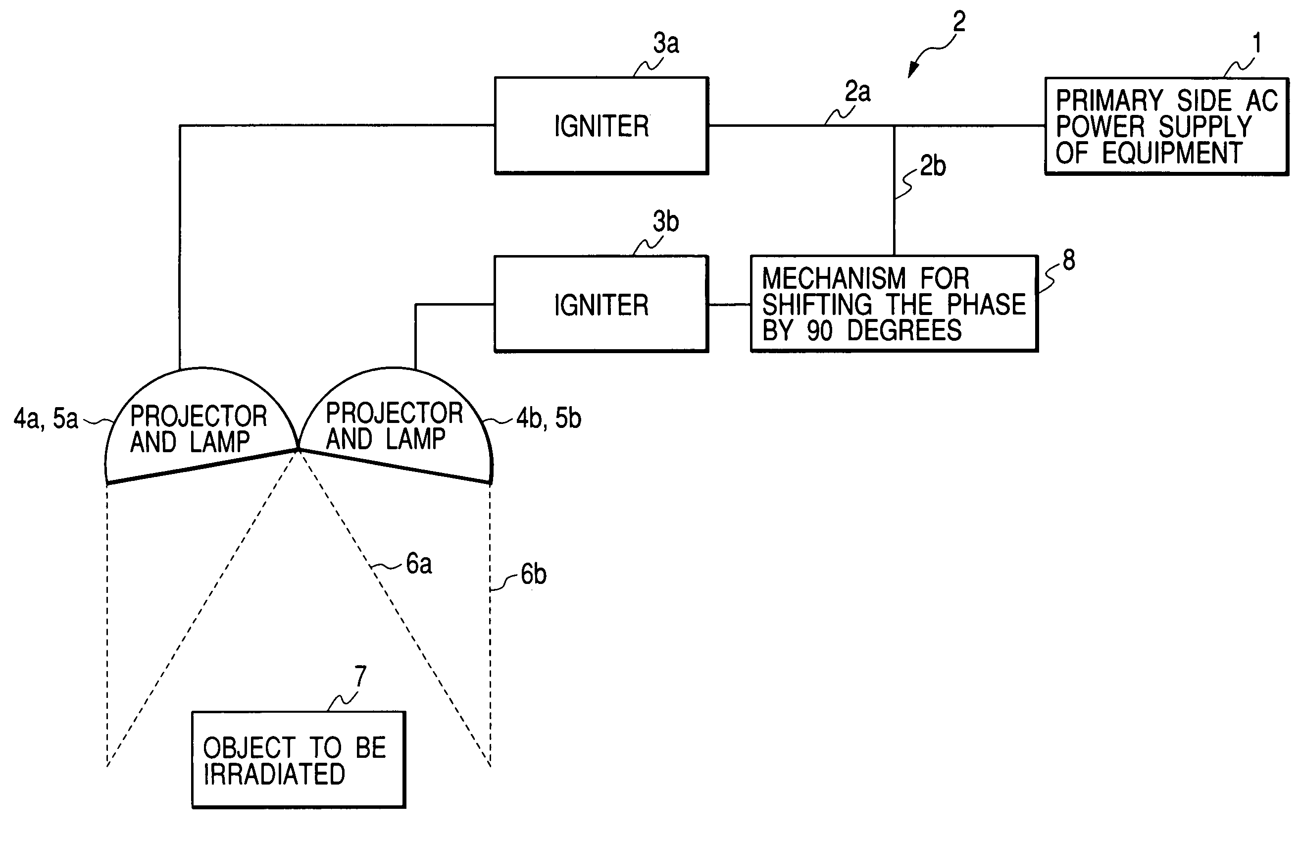
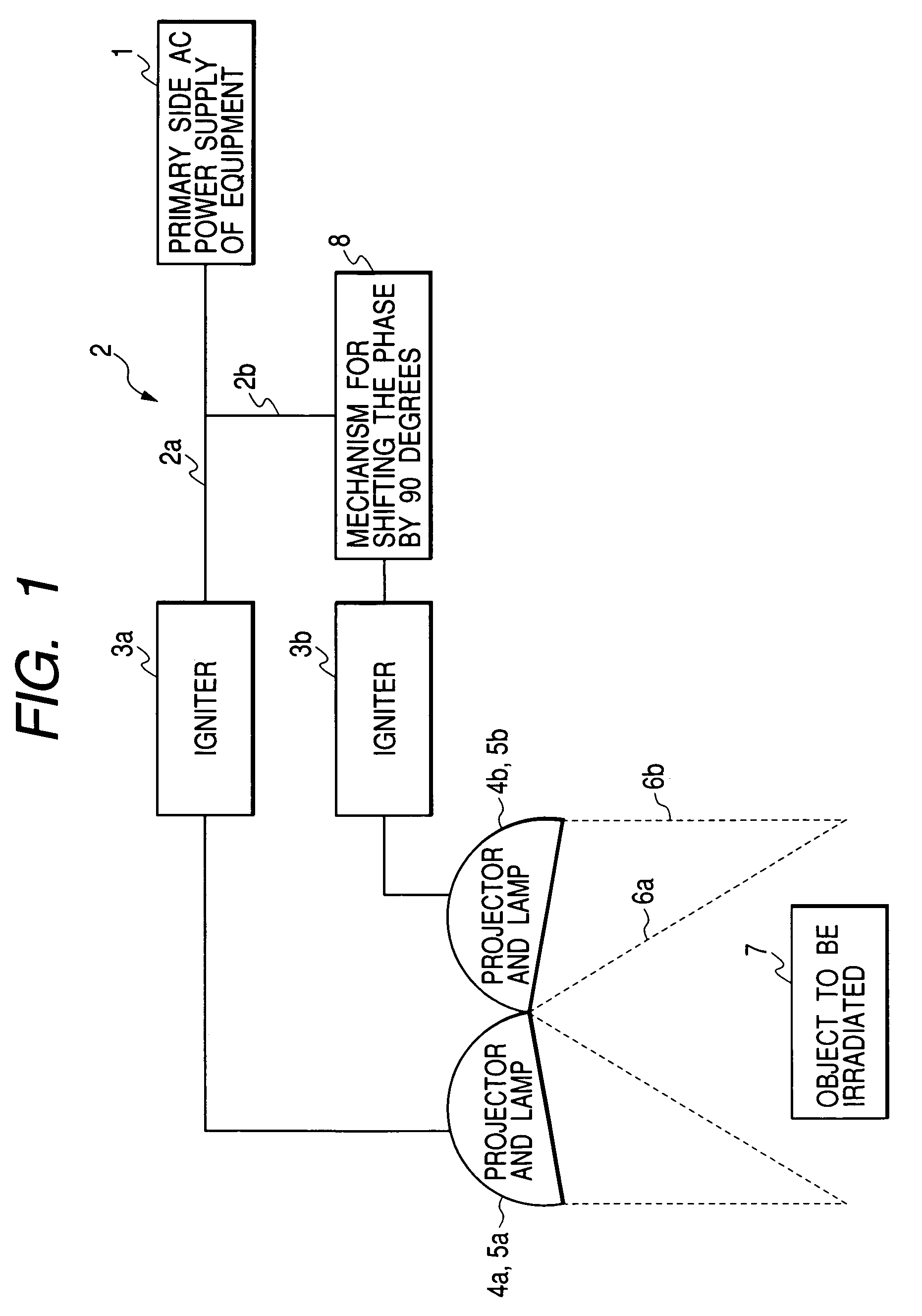
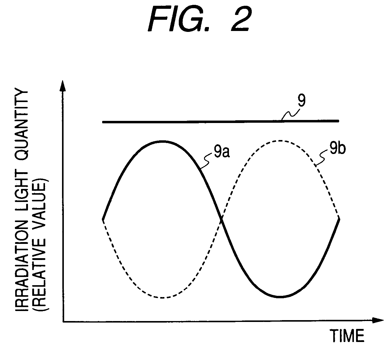
[0060]FIG. 1 is a schematic view of a method and apparatus for irradiating light according to first embodiment of the present invention. FIG. 2 is a graph showing a relationship between irradiation light quantity acquired at the position of the object to be irradiated in FIG. 1 and time. FIG. 14 is a schematic view of a method and apparatus for irradiating light according to comparative example 1 and FIG. 15 is a graph showing a relationship between irradiation light quantity acquired at the position of the object to be irradiated in FIG. 14 and time.

[0061]In Embodiment 1 and comparative example 1, a metal halide lamp which is lit with an AC through an igniter was used as a light source. The metal halide lamp can be lit through an inexpensive igniter, it is growing in light quantity and its spectral distribution is being improved, and in this respect the metal halide lamp is a promising simulated solar radiation light source. On the other hand, since it has high temporal responsivit...

embodiment 2

[0067]FIG. 3 is a schematic view of a method and apparatus for irradiating light according to second embodiment of the present invention. FIG. 2 is a graph showing a relationship between the irradiation light quantity obtained at the position of the object to be irradiated in FIG. 3 and time as in the case of Embodiment 1. This embodiment has a mode of power supply slightly different from that of Embodiment 1 shown in FIG. 1.

[0068]In Embodiment 2 shown in FIG. 3, power supplied from a primary side AC power supply of equipment 1 is supplied to lamps 5a and 5b in two projectors 4a and 4b through electric wirings 2a and 2b and igniters 3a and 3b. As the primary side AC power supply of equipment 1, a three-phase AC is used here. If the phase of the AC supplied to the lamp 5a is set as a reference (0 degree), the AC supplied to the lamp 5b uses a phase different from the reference phase by 120 degrees and by providing a mechanism 8 for shifting the phase by 30 degrees at some midpoint of...

embodiment 3

[0070]FIG. 4 and FIG. 5 are schematic views of a method and apparatus for irradiating light according to a third embodiment of the present invention. FIG. 6 is a graph showing a relationship between the irradiation light quantity obtained at the position of an object to be irradiated in FIG. 4 and time. As in the case of Embodiment 1, Embodiment 3 also uses a metal halide lamp which is lit with an AC through an igniter as the light source.

[0071]In Embodiment 3 shown in FIG. 4, FIG. 5 and FIG. 6, power supplied from a primary side AC power supply of equipment 1 is supplied to lamps 5a, 5b and 5c in three projectors 4a, 4b and 4c through electric wirings 2a, 2b and 2c and igniters 3a, 3b and 3c. As the primary side AC power supply of equipment 1, a three-phase AC is used here. If the phase of the AC supplied to the lamp 5a is set as a reference (0 degree), the AC supplied to the lamp 5b uses a phase different from the reference phase by 120 degrees and the AC supplied to the lamp 5c u...


PUM


Abstract

In a method of irradiating an object with simulated solar radiation using a plurality of light sources, the object is irradiated with simulated solar radiation resulting from superimposed light rays from a plurality of light sources including light sources having different times at which light emission output reaches a peak.

Description

BACKGROUND OF THE INVENTION[0001]1. Field of the Invention[0002]The present invention relates to a method and apparatus for irradiating an object with temporally stable light, and more particularly, to a method and apparatus for irradiating simulated solar radiation, which needs to be irradiated in large light quantity and over a large area, in temporally stable light quantity and spectrum. The present invention also relates to a method and apparatus for irradiating a semiconductor device which is an object temporally responding relatively quickly to a temporal variation in light quantity over a sensitive wavelength range with temporally stable light.[0003]2. Related Background Art[0004]As a method for irradiating a semiconductor device with simulated solar radiation, Japanese Patent Application Laid-Open No. S61-269801 discloses a method of lighting and irradiation using a xenon lamp as a light source, using an expensive air mass filter for adjusting a spectral distribution and usi...

Claims


Application Information

Patent Timeline
Patent Type & Authority Patents(United States)
IPC IPC(8): H01L21/66A61N5/06G01R31/26F21S2/00F21S8/00F21Y101/00H01L31/04H05B37/02
CPCF21S8/006H05B37/029H05B37/02H05B47/155H05B47/10
Inventor TOKUTAKE, NOBUOHASEBE, AKIO
Owner CANON KK
Why Eureka
Try Eureka