Storage device, control device, control method, and program

a storage device and control device technology, applied in the direction of recording information storage, maintaining head carrier alignment, instruments, etc., can solve the problems of not being able to perform, the flying height of the floating distance cannot be set lower than the common range, and the clearance cannot be measured, so as to achieve accurate measurement, uniform recording/reproduction characteristics, and head deterioration

Inactive Publication Date: 2008-09-16
KK TOSHIBA
View PDF17 Cites 37 Cited by
  • Summary
  • Abstract
  • Description
  • Claims
  • Application Information

AI Technical Summary

Benefits of technology

[0007]According to the present invention to provide a storage device, a control method, and a program which can precisely measure the clearance between a head in a floating state and a recording medium surface and perform highly precise control such that a target clearance is achieved upon recording and reading by controlling the amount of electric power distribution to a heater which is provided in a head.
[0069]The present invention provides a control device (MPU). The present invention is a control device of a storage device having a head having at least either one of a reading element and a recording element and provided with a heater for changing a projection distance protrusion value by thermal expansion accompanying electric-power-distributed heating for accessing data by floating above a rotating recording medium, wherein the control device is characterized by having a clearance information measurement unit for measuring clearance information required for controlling a clearance between the reading element and the recording medium upon desired correction; and a clearance control unit for controlling the clearance to a predetermined target clearance upon reproduction or recording by changing the projection distance protrusion value of the head by varying the amount of electric power distributed to the heater. According to the present invention, for example in an examination process or the like, regarding the clearance of a head, precisely, the clearance between the reading element and the recording medium surface, a clearance changed distance is measured while the head is caused to expand and project by increasing the amount of electric power distributed to the heater, contact of the head projected part with the medium or a state immediately before that is determined when a value obtained by differentiating the clearance changed distance is reduced to equal to or less than a threshold value, and the clearance changed distance at that point is set as a clearance measured value of the head; thus, the clearance can be accurately measured for a floating head. Moreover, in addition to the measurement of the clearance do of the head, the recording current projection distance protrusion value dw, the heater projection sensitivity protrusion sensitivity e, the projection transition time tp, the first temperature correction coefficient Kd, and the second temperature correction coefficient Ke are measured as the clearance control information required for clearance control; thus, highly precise clearance control is realized such that control is performed by use of the parameters such that the write target clearance is achieved at the write target sector upon recording and the read target clearance is achieved at the read target sector upon reading. When the clearance of the head is controlled to a constant target clearance in this manner, a uniform recording / reproduction characteristic can be obtained even when heads in which variation is generated in the floating distance flying height are used, and head deterioration due to medium contact can be avoided; as a result, the head yield is improved and the cost can be reduced. The above and other objects, features, and advantages of the present invention will become more apparent from the following detailed description with reference to the drawings.

Problems solved by technology

However, when the floating distance flying height of the head is reduced, collision with minute protrusions on the magnetic disk surface is readily generated, and variation of the clearances between heads is present in the range of mechanical common differences; therefore, there is a problem that the floating distance flying height cannot be set lower than the range of common differences when the medium contact is taken into consideration.
However, in such conventional methods of controlling the clearance between the head and the magnetic disk recording surface, basically, the projection distance protrusion value is adjusted such that reproduction can be performed without causing medium contact by utilizing that the clearance is changed due to expansion / projection of the head floating surface along with heating of the heater caused by electric power distribution; and there has been a problem that highly precise clearance control of controlling the clearance upon recording and reproduction to a constant target clearance by taking variation of the clearances which are different in each head into consideration cannot be performed.
However, in recent magnetic disk devices, contact-start-stop of the head is abolished, and a head retained in a ramp load mechanism is delivered to the disk surface upon activation of the device in the state in which the magnetic disk is rotating, thereby causing it to float from the beginning; thus, there is a problem that the amplitude change at the time when the head which is in contact with the magnetic disk surface floats cannot be detected, and the clearance cannot be measured from unchanged amplitude of the reproduction signal of the head which is floating with a constant clearance.

Method used


Image

  • Storage device, control device, control method, and program
  • Storage device, control device, control method, and program
  • Storage device, control device, control method, and program

Examples


Embodiment Construction

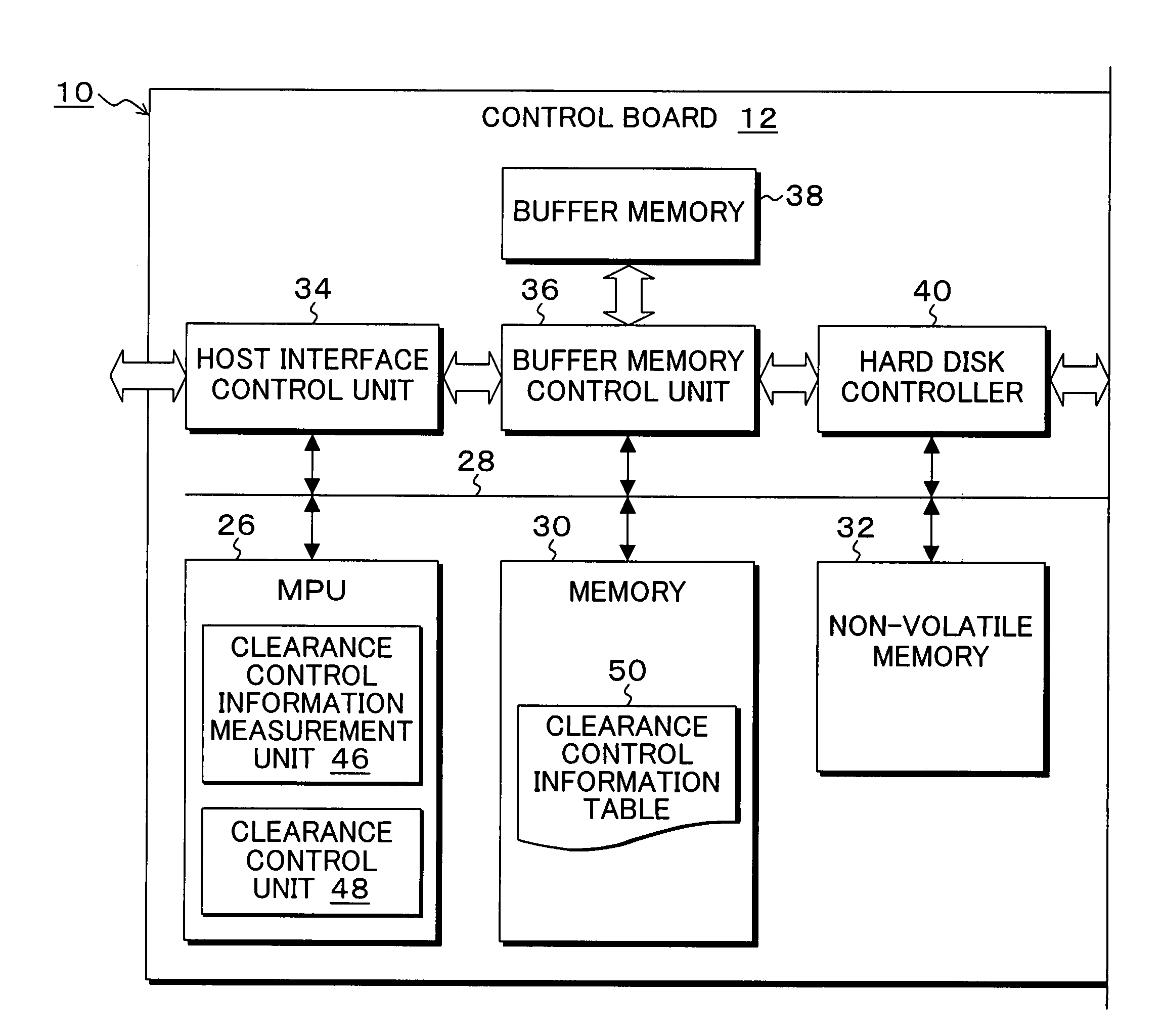
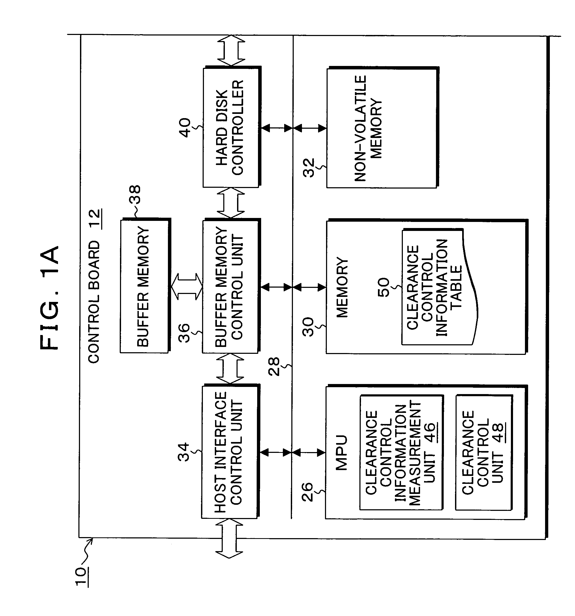
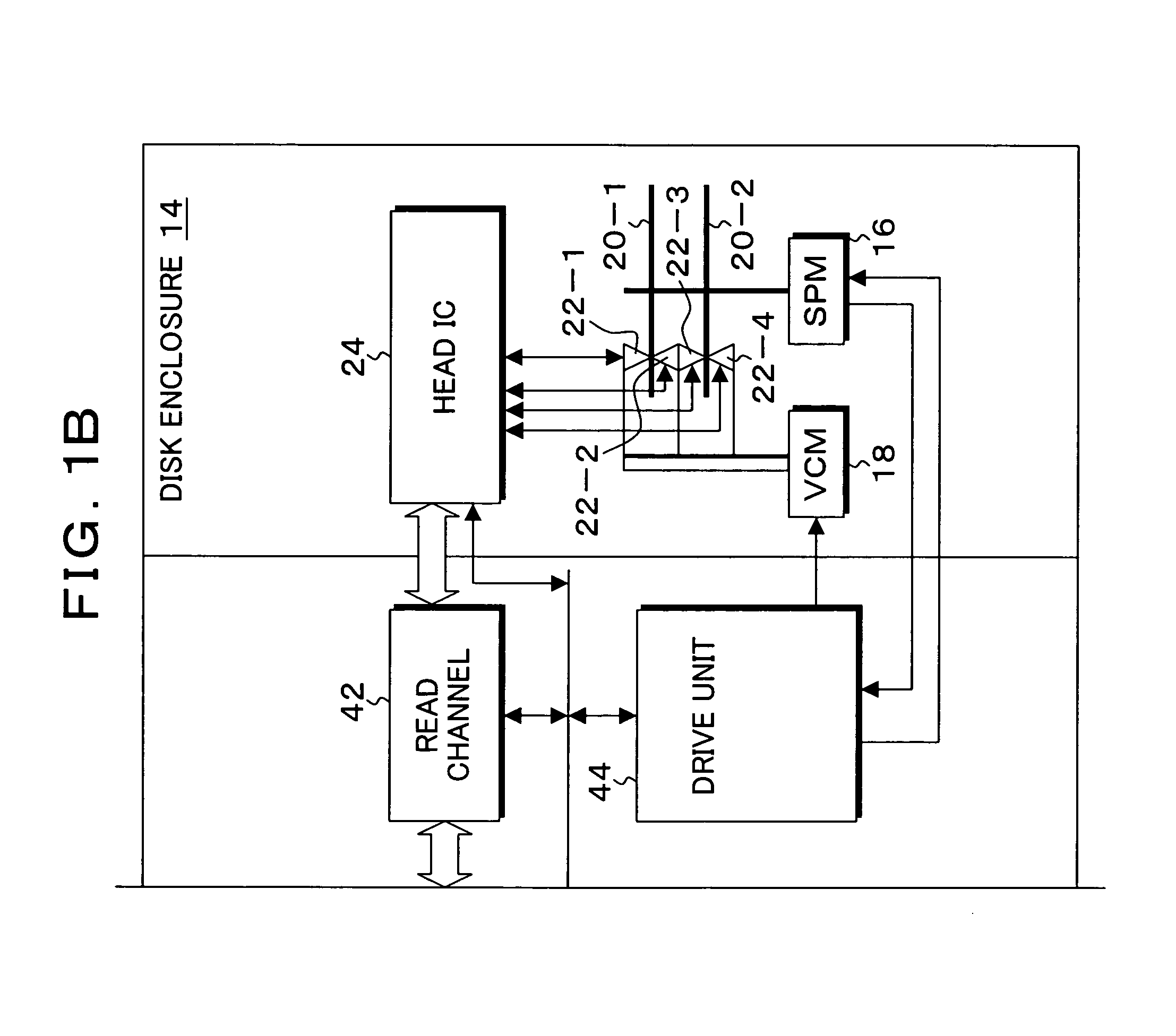
[0096]FIGS. 1A and 1B are block diagrams showing an embodiment of a magnetic disk device according to the present invention. In FIGS. 1A and 1B, the magnetic disk device 10 which is known as a hard disk drive (HDD) is comprised of a disk enclosure 14 and a control board 12. A spindle motor (SPM) 16 is provided in the disk enclosure 14; and magnetic disks (storage media) 20-1 and 20-2 are attached to a rotating shaft of the spindle motor 16 and rotated at, for example, 4200 rpm for a certain period of time. In addition, a voice coil motor (VCM) 18 is provided in the disk enclosure 14, wherein the voice coil motor 18 has distal ends of arms of head actuators on which heads 22-1 to 22-4 are loaded so as to perform positioning of the heads with respect to recording surfaces of the magnetic disks 20-1 and 20-2. In addition, recording elements and reading elements are loaded on the heads 22-1 to 22-4 in an integrated manner.

[0097]The heads 22-1 to 22-4 are connected to a head IC 24 by sig...


PUM

PropertyMeasurementUnit
floating distanceaaaaaaaaaa
temperatureaaaaaaaaaa
electric poweraaaaaaaaaa

Abstract

A heater for changing a projection distance protrusion value by thermal expansion accompanying electric-power-distributed heating is embedded in a head having a reading element and a recording element. A clearance control information measurement unit measures and saves, at desired correction timing, clearance control information including a clearance required for controlling the clearance between the reading element and the recording medium, heater projection sensitivity protrusion sensitivity, projection distance protrusion value transition time, recording current projection distance protrusion value, and a temperature correction coefficient. The clearance control unit varies the electric power distributed to the heater and changes the projection distance protrusion value of the head, thereby controlling the clearance to a target clearance upon reproduction and recording.

Description

[0001]This application is a priority based on prior application No. JP 2006-088677, filed Mar. 28, 2006, in Japan.BACKGROUND OF THE INVENTION[0002]1. Field of the Invention[0003]The present invention relates to a storage device for reading / writing data by floating a head with a flying head above a rotating recording medium, and particularly relates to a storage device, a control method, and a program for controlling the clearance between the head and the recording medium, the head-disk clearance to a predetermined target clearance by changing the projection distance protrusion value by thermal expansion accompanying heating of a heater provided in a head caused by electric power distribution.[0004]2. Description of the Related Arts[0005]Conventionally, the floating distance flying height of the head with respect to the recording surface of a magnetic disk has to be reduced in order to realize a high recording density of the magnetic disk device, and a floating distance flying height...

Claims


Application Information

Patent Timeline
Patent Type & Authority Patents(United States)
IPC IPC(8): G11B21/02
CPCG11B5/6064G11B5/6005G11B21/21G11B5/012G11B5/60G11B5/40
Inventor YAMASHITA, SATOSHISAITOU, SHUNJIABE, YUKIOYANAGI, SHIGENORI
Owner KK TOSHIBA
Why Eureka
Try Eureka