Auger finger with resilient elastomeric retainer retractor at breaking point

a technology of resilient elastomeric retainers and finger rings, which is applied in the direction of rolling carts, agriculture tools and machines, loading/unloading, etc., can solve the problems of finger breaking at the failure region, damage or jamming other components, and difficulty in finding and retrieving, so as to facilitate the retraction limit or prevent the free flailing of the free end portion, and the effect of simple construction

Active Publication Date: 2008-09-23
BLUE LEAF I P INC
View PDF19 Cites 13 Cited by
  • Summary
  • Abstract
  • Description
  • Claims
  • Application Information

AI Technical Summary

Benefits of technology

[0006]What is disclosed is an auger finger with a resilient elastomeric retainer retractor for retaining a broken free end thereof, which overcomes one or more of the problems and disadvantages set forth above, and which is additionally operable for automatically and controllably retracting the broken free end into a rotating auger drum and subsequently retaining the broken free end within the drum, and which is simple in construction.
[0007]According to a preferred aspect of the invention, the auger finger includes a mounting end portion having a first sectional extent, an elongate free end portion opposite the mounting end portion, and a failure region disposed between and connecting the elongate free end portion with the mounting end portion. The failure region preferably has a second sectional extent smaller and weaker than the first sectional extent, or is otherwise weakened, so as to break and release the free end portion from the mounting end portion when the finger is subjected to a predetermined side loading condition, representative of contact with an obstruction. And, the auger finger includes at least one elastomeric retainer retractor connected to the free end portion and to the mounting end portion and spanning the failure region, the retainer retractor being constructed and operable such that, when the failure region is broken, the retainer retractor will retain the free end portion, while being resiliently flexible for allowing relative pivotal movement therebetween in a manner that facilitates retraction of the free end portion into the drum, but which substantially limits or prevents free flailing of the free end portion while extending from the drum, and after retraction into the interior thereof.
[0008]More particularly, the mounting end portion of the auger finger is preferably adapted to be mounted within a drum of an auger in connection with a support element offset axially from a rotational axis of the drum such that the failure region is also located within the drum, and the free end portion projecting radially outwardly from the drum. Importantly, in the event of breakage or failure of the failure region, the elastomeric retainer retractor connected between the free end and mounting end portions and spanning the failure region, will be capable of holding the free end portion in connection with the mounting end portion, including in opposition to forces generated as a result of rapid energy release from the breakage such that the free end portion will not fly from the drum or otherwise be lost. Further, during subsequent rotation of the drum, the retainer retractor will allow relative pivotal movement of the free end portion and the mounting end portion, and preferably at least some limited relative longitudinal movement therebetween, as required, to facilitate and control automatic retraction of the free end portion into the drum and holding of the free end in a suitable position therein, such that the finger will not undesirably flail about the exterior of the drum during subsequent rotation, or, become loosened and lost or inducted into a threshing system of a combine with which the finger is used, or flail about inside the drum when retracted therein.
[0010]According to other preferred aspects of the invention, the rubber member includes one or more windows or openings therein beside the failure region of the finger, preferably facing in a predetermined direction which is the rotational direction of the drum and the opposite direction, such that, in the event of breakage of the finger, the portion or portions of the retainer retractor in the vicinity of the broken region will be less likely to be pinched between the relatively pivoting portions of the finger and punctured and / or torn by sharp edges and / or points on the thus exposed surface or surfaces thereof, or by elements or particles such as shards of the finger that may break from the finger and fly or be propelled therefrom. This directional orientation can be established when the finger is mounted in the drum. In its free state, the tubular member will retain its original tubular shape, but when subjected to bending forces resulting from bending and breaking and subsequent pivoting of the broken end portions of the finger, the portion or portions of the tubular member spanning the broken failure region are configured so as to correspondingly resiliently bend or flex while holding the broken off free end portion of the finger in connection with the mounting end portion. In a further preferred embodiment, the element or elements spanning the failure region are configured and sufficiently strong and robust for controlling relative pivotal movements of the portions of the broken finger, so as to be limited at least generally, to the direction of rotation of the drum and the opposite direction.
[0011]In still another preferred embodiment, the rubber member includes portions attached or connected to the free and mounting end portions of the finger, which preferably comprise tubular members or bands which extend therearound and are securely affixed or attached thereto using any of the above described techniques, and at least one resilient elastomeric element or tether connected to and extending between the tubular members or bands in spanning relation to the failure region, thereby defining the desired opening or openings next to the failure region. More preferably, two tethers are provided, located on opposite sides of the failure region, such that the opening or openings face both in the direction of movement, and in the opposite direction, such that contact between portions of the retainer retractor and any sharp edges or points and other projectiles emanating from the breakage region can be avoided or substantially limited if breakage occurs. Again, this directional orientation can be established when the finger is installed in the drum. The tether or tethers also preferably extend and are spaced sidewardly outwardly of the failure region, and include rounded surface portions facing the failure region, so as to lessen the possibility of damage thereto from sharp or pointy edges and or separated elements. The elements or tethers while sufficiently flexible to allow pivotal movement of the broken finger portions, are also preferably sufficiently robust so as to be capable of exerting a centering force on the broken free end portion for substantially limiting relative pivotal movements at least generally or largely to the direction of rotation of the drum and the opposite direction, and also for reducing random flailing of the broken free end portion.

Problems solved by technology

It is additionally well known to provide a failure region at a predetermined location along the length of such fingers, such as a groove or the like, such that, in the event that a large, solid or hard object such as a stone or rock, a stump or fence post or fragment thereof, an animal skeleton or part thereof, or the like, is encountered and attempted to be raked by a finger, forces exerted by the rotation of the drum applied through the finger against the object, if sufficiently strong, will cause the finger to break at the failure region.
However, in the event of breakage of the finger, the broken free end of the finger can undesirably flail about the exterior of the drum during the rotation thereof, so as to strike the floor or pan of the header during the rotation resulting in annoying noise, or, if the free end falls into the drum, it can undesirably move around freely therein so as to also create annoying noise, and it can possibly damage or jam other components located therein, and be difficult to find and retrieve.

Method used


Image

  • Auger finger with resilient elastomeric retainer retractor at breaking point
  • Auger finger with resilient elastomeric retainer retractor at breaking point
  • Auger finger with resilient elastomeric retainer retractor at breaking point

Examples


second embodiment

[0054]Referring to FIGS. 17, 17a and 17b, auger finger 48 is shown including a retainer retractor 84 constructed and operable according to the teachings of the present invention, like parts of retainer retractor 84 and retainer retractor 66 being identified by like numbers. Retainer retractor 84 is connected between mounting end portion 52 and free end portion 54 of auger finger 48, so as to span failure region 56 thereof and hold or retain free end portion 54 in the event failure region 56 is broken, as illustrated in FIGS. 17a and 17b. Retainer retractor 84 has resilient properties to move with and thereby allow relative pivotal movement of broken apart mounting end portion 52 and free end portion 54 (FIG. 17b), to allow passage of free end portion 54 over an object (e.g., FIGS. 12 and 13) contact with which caused the breakage of failure region 56 (e.g. resulting from application of a side load C), and to allow and facilitate automatic retraction of free end portion 54 through ho...

third embodiment

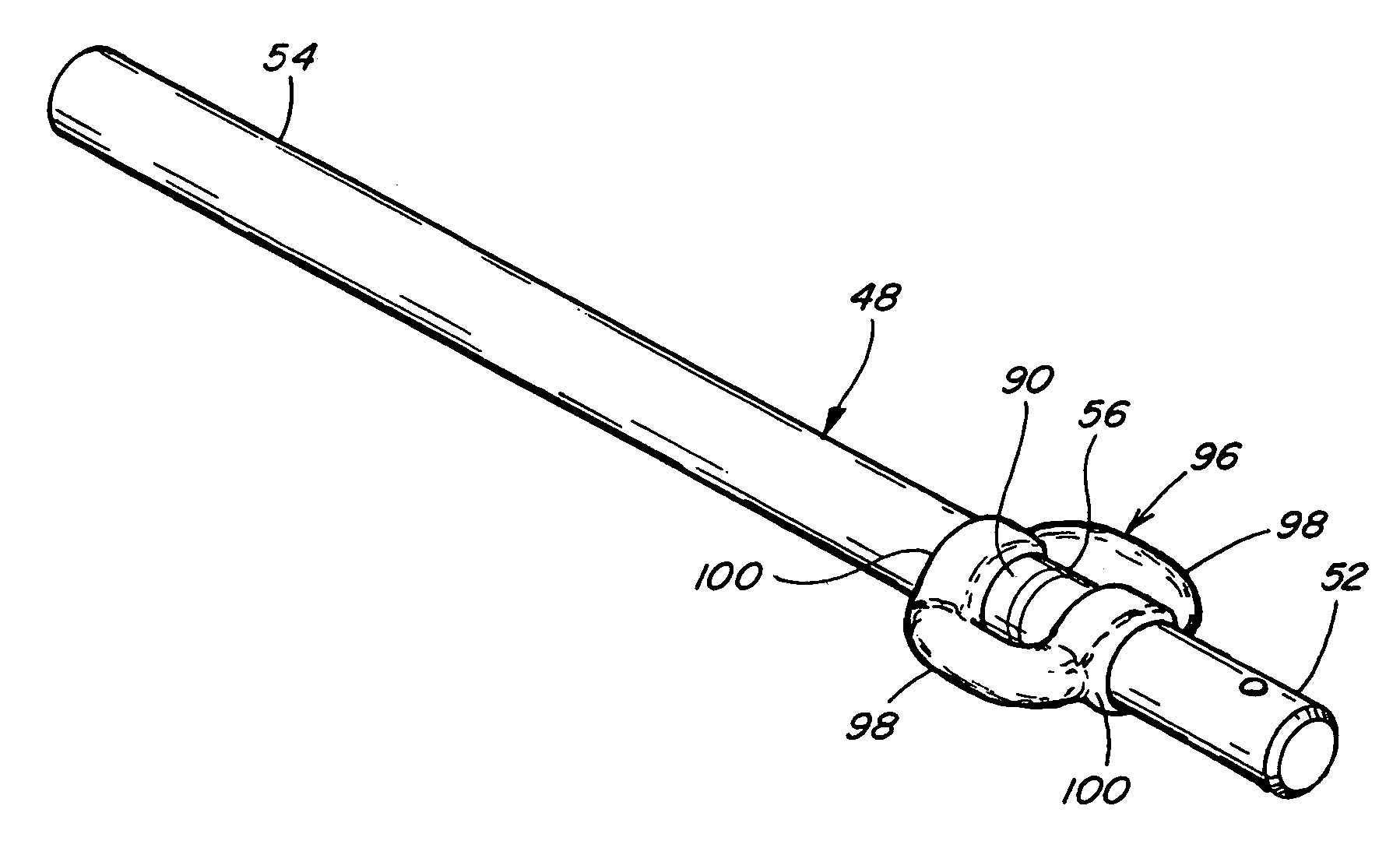
[0055]Referring also to FIGS. 18, 18a, 18b, 18c and 18d, auger finger 48 is shown including a retainer retractor 96 constructed and operable according to the teachings of the present invention, like parts of retainer retractor 96 and retainer retractors 66 and 84 being identified by like numbers. Retainer retractor 96 is connected between mounting end portion 52 and free end portion 54 of auger finger 48, so as to span failure region 56 thereof and hold or retain free end portion 54 in the event failure region 56 is broken, as illustrated in FIGS. 18c and 18d. Retainer retractor 96 has resilient properties to allow relative pivotal movement of mounting end portion 52 and free end portion 54, to allow passage of free end portion 54 over an object (e.g., FIGS. 12 and 13) contact with which caused the breakage of failure region 56, and to allow and facilitate automatic retraction of free end portion 54 through hole 46 into internal cavity 58 of drum 36, by continued rotation of the dru...


PUM


Abstract

A finger for a crop gathering auger of a grain header for an agricultural combine, a forage harvester, or the like, the finger including a resilient elastomeric retainer retractor which spans a failure region of the finger and will retain a free end of the finger in connection with a mounting end thereof when the failure region is broken, and which is configured and operable for automatically retracting the broken off free end into an auger drum and retaining it therein during subsequent rotation of the drum for limiting potential damage from the broken end and preventing entry of the broken end into crop handling equipment of the combine or other machine.

Description

TECHNICAL FIELD[0001]This invention relates generally to a finger for a crop gathering auger of a grain header for an agricultural combine, and more particularly, to an auger finger including a resilient elastomeric retainer retractor which spans a failure region of the finger and will retain and allow resilient pivotal movement of a free end of the finger in connection with a mounting end thereof when the failure region is broken without the retainer retractor itself being subject to failure as a result of the breakage of the failure region, and which is preferably additionally operable for automatically controllably retracting the broken off free end into an auger drum and retaining it therein during subsequent rotation of the drum for limiting potential damage from the broken end and preventing entry of the broken end into crop handling equipment of the combine.BACKGROUND ART[0002]It is well known to provide stiff, hard fingers of steel or other rigid material protruding radially...

Claims


Application Information

Patent Timeline
Patent Type & Authority Patents(United States)
IPC IPC(8): A01D43/02A01D89/00
CPCA01D75/182A01D61/008
Inventor BICH, GARY L.EKIS, IMANTSFIGGINS, RYANRAYFIELD, JAMES F.
Owner BLUE LEAF I P INC
Why Eureka
Try Eureka