Mounting structure for vehicle battery pack

a battery pack and mounting structure technology, applied in the direction of roofs, cell components, cell component details, etc., can solve the problems of damage, main body of battery packs or surrounding cooling pipes may be kicked, etc., to prevent damage, prevent the effect of device units from being kicked, and avoid damage by kicking

Inactive Publication Date: 2008-09-23
TOYOTA JIDOSHA KK
View PDF13 Cites 27 Cited by
  • Summary
  • Abstract
  • Description
  • Claims
  • Application Information

AI Technical Summary

Benefits of technology

[0007]The present invention has been made to solve the aforementioned problem, and one object of the present invention is to provide a mounting structure for a vehicle battery pack preventing damage to the vehicle battery pack and having improved safety.
[0009]In the mounting structure for a vehicle battery pack formed as described above, since the protection member is provided on the vehicle rear side relative to the vehicle battery pack, it can protect the vehicle battery pack against an impact from behind. For example, the protection member can protect the vehicle battery pack against a kick by a passenger in a rear seat. Further, when the vehicle battery pack is provided under a seat in the last row, the protection member can prevent the vehicle battery pack from being hit by luggage and others in a trunk room.
[0011]More preferably, the protection member is fastened to the body. In this case, fastening the protection member to the body eliminates the need to reinforce the vehicle battery pack itself. Therefore, weight reduction can be achieved.
[0014]In the vehicle battery pack formed as described above, since the device unit is provided on the vehicle rear side, a footrest for a passenger in the second seat can be obtained. Further, damage by a kick can be avoided.
[0015]Preferably, a distance from a bottom surface of the first seat to a top of the device unit is greater than a distance from the bottom surface of the first seat to a top of the battery main body unit. In this case, since the distance from the bottom surface of the first seat to the top of the device unit is greater, a passenger can easily insert his / her feet between the bottom surface of the first seat and the device unit. Also, this structure can suppress the device unit from being kicked. Further, since there is a greater distance from the toe of a passenger to the vehicle battery pack, damage can be prevented.

Problems solved by technology

In a conventional mounting structure, however, the battery is placed at a position where a footrest for a passenger in a rear seat is placed, and the main body of a battery pack or a surrounding cooling pipe may be kicked and damaged.

Method used


Image

  • Mounting structure for vehicle battery pack
  • Mounting structure for vehicle battery pack
  • Mounting structure for vehicle battery pack

Examples


first embodiment

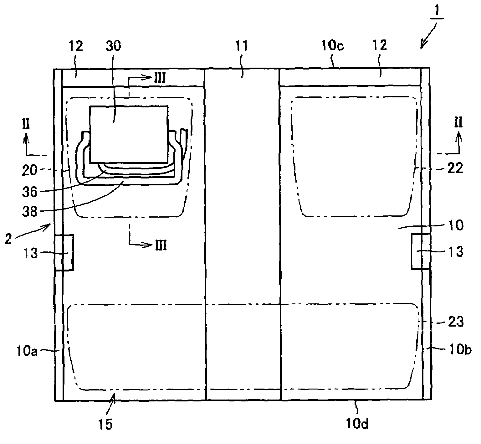
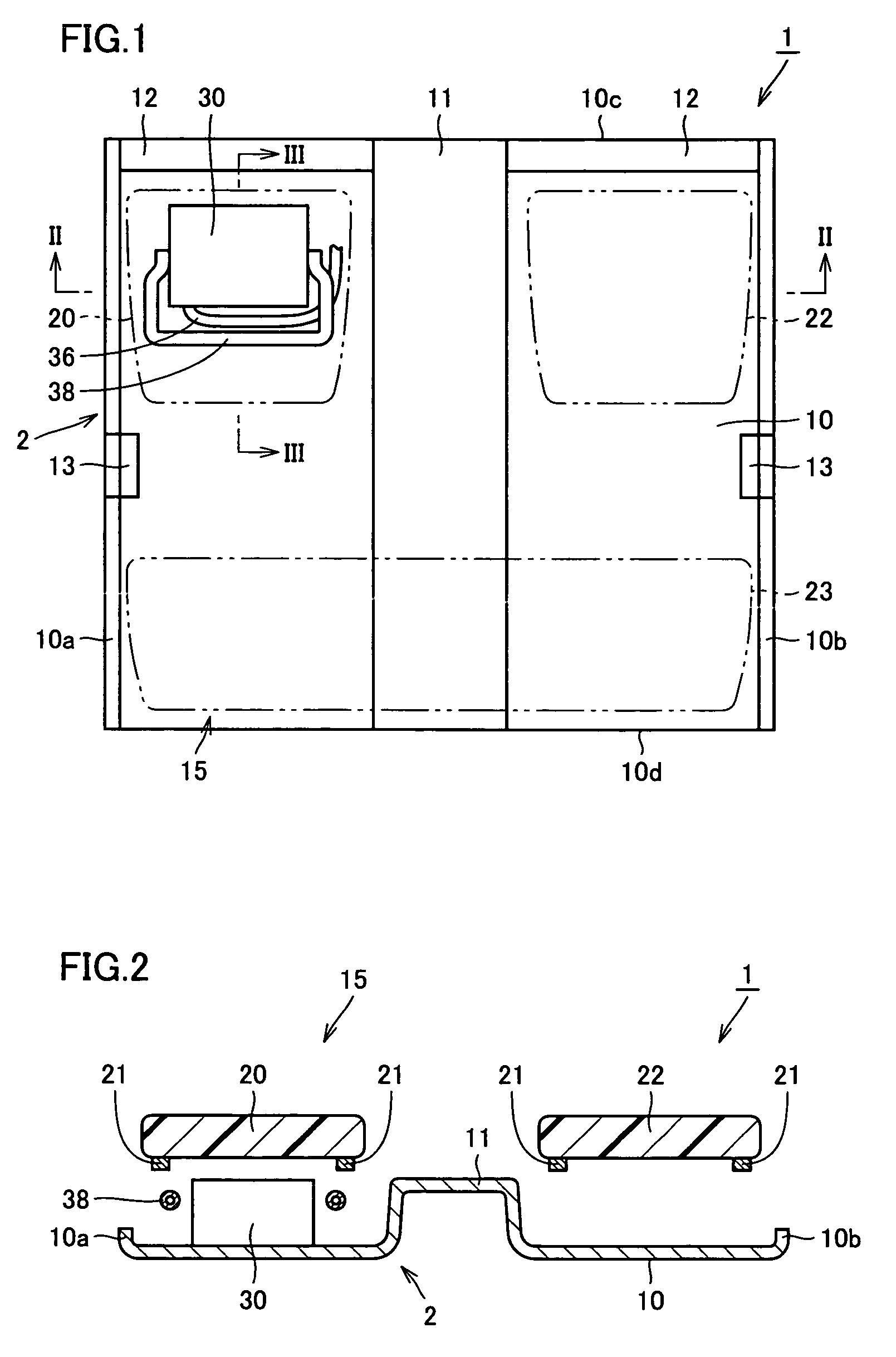
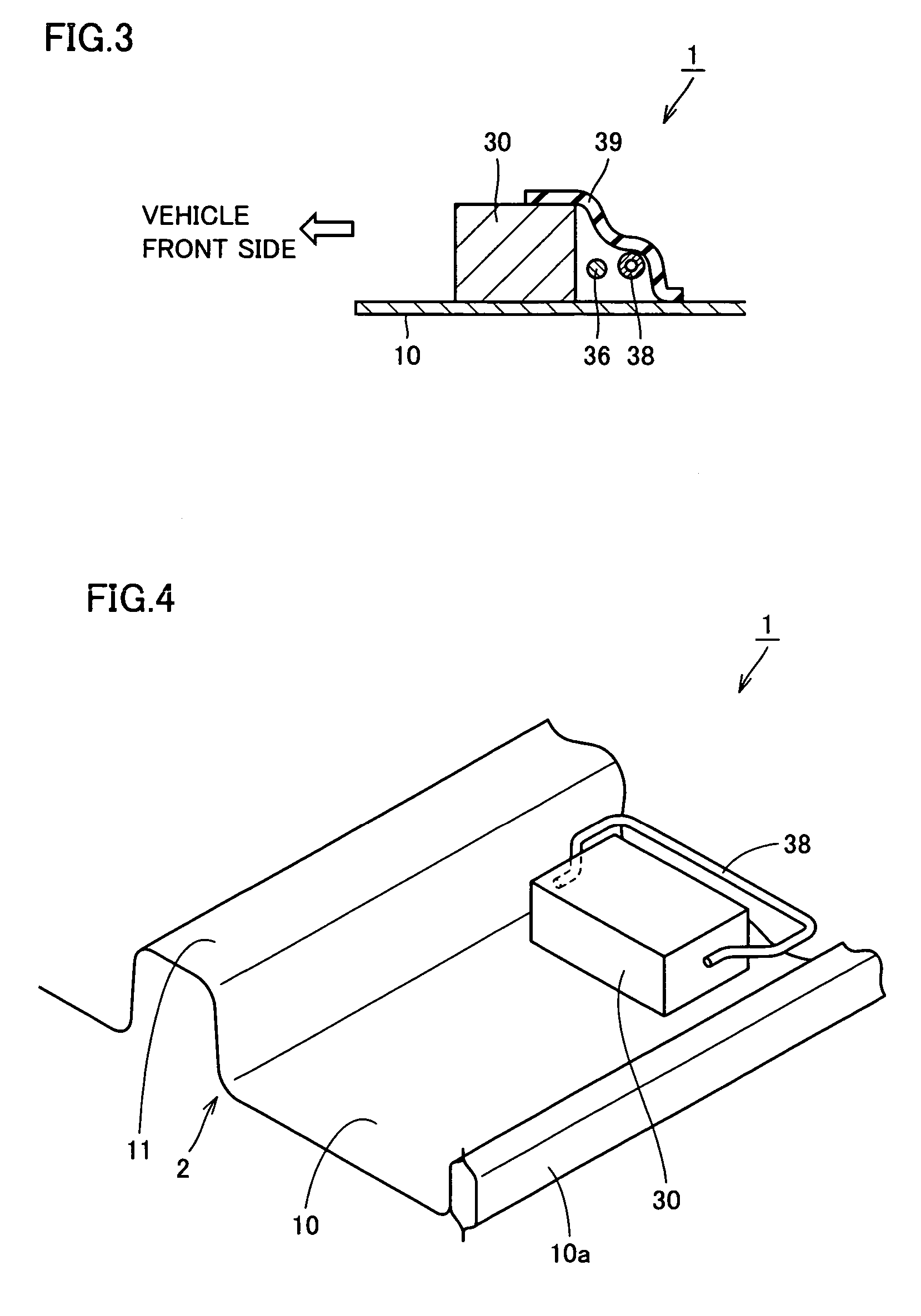
[0034]FIG. 1 is a plan view of a mounting structure for a vehicle battery pack in accordance with a first embodiment of the present invention. Referring to FIG. 1, a mounting structure 1 for a vehicle battery pack in accordance with the first embodiment of the present invention includes a body 2 forming a vehicle body and having a floor panel 10, a front seat 20 as a seat provided on floor panel 10, a vehicle battery pack 30 provided under front seat 20, and a protection member 38 provided on a vehicle rear side relative to vehicle battery pack 30 and protecting vehicle battery pack 30.

[0035]In a cabin 15, a tunnel 11 is provided on floor panel 10 of body 2, extending from a vehicle front portion 10c to a vehicle rear portion 10d. Vehicle front portion 10c is located on a vehicle front side, and vehicle rear portion 10d is located on the vehicle rear side. Tunnel 11 is provided to be raised from the surface of floor panel 10, serving to increase the strength of floor panel 10. Furth...

second embodiment

[0047]FIG. 6 is a perspective view of a mounting structure for a vehicle battery pack in accordance with a second embodiment of the present invention. FIG. 7 is a plan view of the mounting structure for a vehicle battery pack seen from a direction indicated by arrow VII in FIG. 6. Referring to FIGS. 6 and 7, mounting structure 1 for a vehicle battery pack in accordance with the second embodiment of the present invention is different from the mounting structure for a vehicle battery pack in accordance with the first embodiment in that protection member 38 is directly fastened to body 2. Specifically, in the second embodiment, protection member 38, which is a pipe-shaped protector, is attached to tunnel 11 and rocker 10a of body 2. To attach protection member 38, various joining methods which have been conventionally used, such as welding, riveted joint, or bolt connection can be used. It is to be noted that, in the first and the second embodiments, wire harness 36 may not be provided...

third embodiment

[0049]FIG. 8 is a plan view of a mounting structure for a vehicle battery pack in accordance with a third embodiment of the present invention. FIG. 9 is a cross sectional view seen along the line IX-IX in FIG. 8. Referring to FIGS. 8 and 9, the mounting structure for a vehicle battery pack in accordance with the third embodiment of the present invention is different from the mounting structures for a vehicle battery pack in accordance with the first and the second embodiments in that protection member 38 is attached to a seat rail 21. Since seat rail 21 is attached to floor panel 10, protection member 38 is attached to floor panel 10 via seat rail 21. Although protection member 38 is linear in FIGS. 8 and 9, it is not limited to this shape, and it may be in a meander shape. It may also be in a zigzag shape or a crank shape. Further, protection member 38 does not necessarily have a uniform thickness, and it may have a thick portion and a thin portion.

[0050]The mounting structure for ...


PUM

PropertyMeasurementUnit
distanceaaaaaaaaaa
shapeaaaaaaaaaa
weightaaaaaaaaaa

Abstract

To provide a mounting structure for a vehicle battery pack which prevents damage to the vehicle battery pack and has improved safety, a mounting structure for a vehicle battery pack has a body with a floor panel, a front seat provided on the floor panel, a vehicle battery pack provided under the front seat, and a protection member provided on a vehicle rear side relative to the vehicle battery pack and protecting the vehicle battery pack. The protection member can be fastened to the body.

Description

[0001]This is a 371 national phase application of PCT / JP2004 / 017831 filed 24 Nov. 2004, which claims priority to Japanese Patent Application No. JP 2003-399682 filed 28 Nov. 2003, the contents of which are incorporated herein by reference.TECHNICAL FIELD[0002]The present invention relates to a mounting structure for a vehicle battery pack, and more particularly, a mounting structure for a battery pack for a vehicle such as an electric vehicle using a generator as a drive source.BACKGROUND ART[0003]Recently, an electric vehicle using an electric motor as a drive source, and a so-called hybrid vehicle having a plurality of types of drive sources such as an electric motor and a gasoline engine have been in practical use.[0004]Such a vehicle as an electric vehicle is provided with a battery for supplying electricity as energy to a generator or the like. As the battery for this application, a secondary battery capable of being charged and discharged repeatedly, such as a nicad (Ni—Cd) ba...

Claims


Application Information

Patent Timeline
Patent Type & Authority Patents(United States)
IPC IPC(8): B60R27/00B60R99/00B60K1/04B62D25/20H01M50/202H01M50/244H01M50/249
CPCB60K1/04H01M2/1083B62D25/2036B62D25/20B62D25/025Y02E60/10H01M50/249H01M50/202H01M50/244
Inventor WATANABE, KONAGASE, SHUJISHUKUYA, KEIJI
Owner TOYOTA JIDOSHA KK
Why Eureka
Try Eureka