

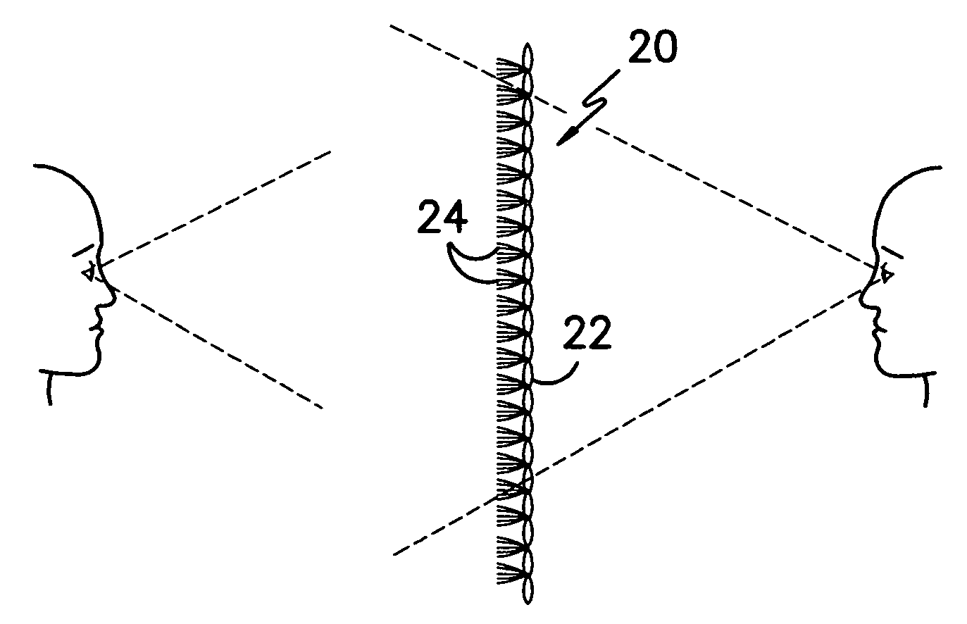
One-way viewable screen
a one-way viewable, screen technology, applied in the direction of knitting, dyeing process, weaving, etc., can solve the problems of material not providing one-way viewing, material rigidity and fragility, and not providing proper one-way see through properties, etc., to achieve high mechanical strength, good air permeability, and particular utility
- Summary
- Abstract
- Description
- Claims
- Application Information
AI Technical Summary
Benefits of technology
Problems solved by technology
Method used
Image

Examples
example
Example 1
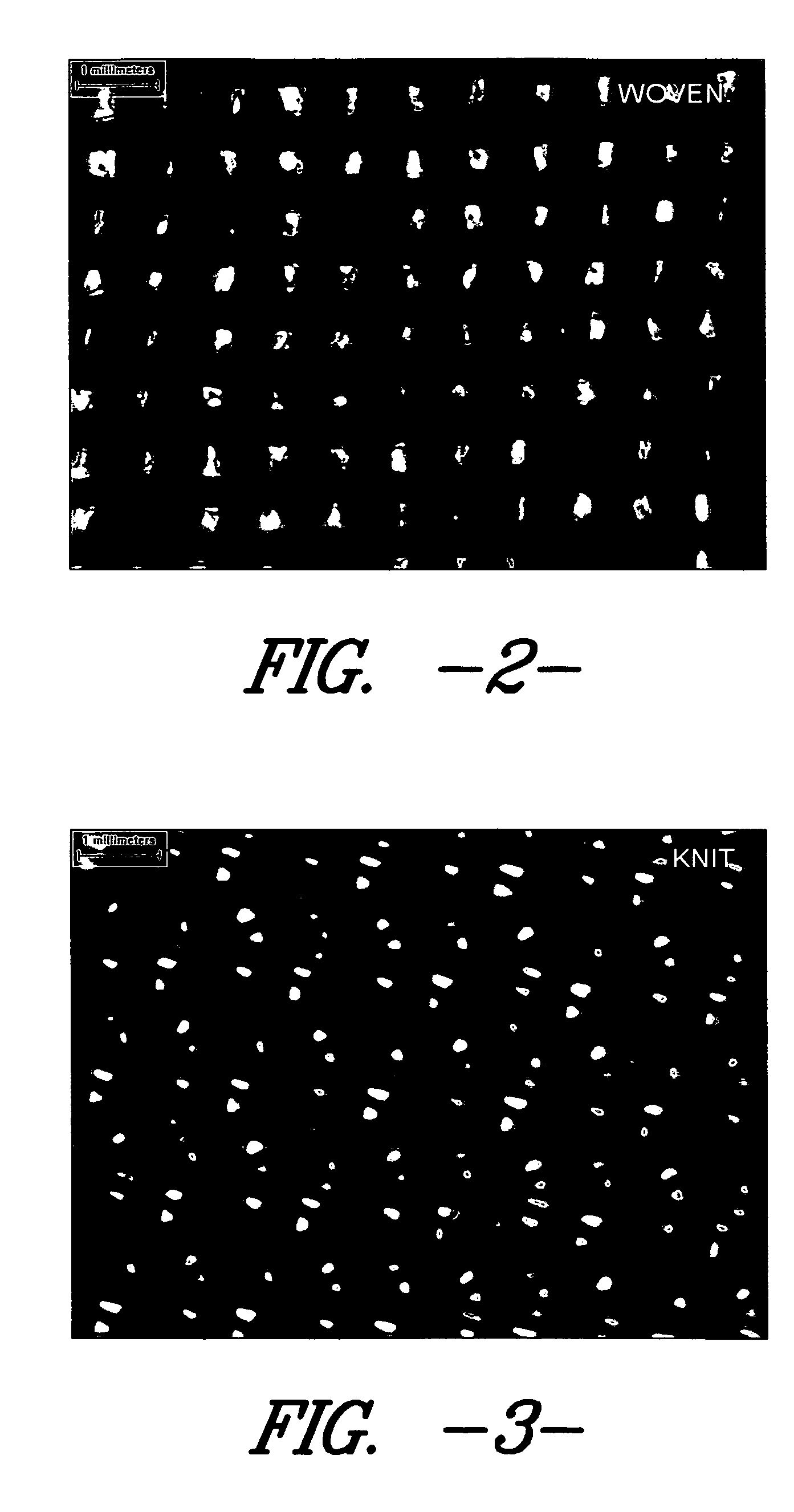
[0039]A plain warp knit fabric having 24 courses by 28 wales per inch was formed by using 3 bars of 1 / 150 / 24 56T (meaning a 1 ply, 150 denier yarn with 24 filaments per yarn of Dacron type 56 round cross-section polyester yarn) yarns and one bar of 1 / 100 / 34 56T background yarn. The fabric had a weight of about 8.88 ounces per square yard. The intersticial openings of the fabric varied mostly in the range of 0.1-0.25 mm, and they are spaced from each other by about 0.3-2 mm as shown in FIG. 3. The fabric was then jet dyed in a conventional manner to a dark black color using black disperse dye such that a low reflectance (approximately 4%) in the visible spectrum is achieved. The fabric was then heat set in a conventional manner on a tenter frame. An aluminum reflective pigment-containing metallic finish spray paint manufactured by Rust-Oleum Corporation was used to spray paint one side of the fabric such that the side was covered with metallic paint. The coated fabric has an...
example 1
Results
[0046]
WavelengthReflectionReflectionRatio - ARatio - BnmTransmission, %on side A, %on side B, %sideside7003.88131.6929.7728.1659366142.5179077566903.69532.1618.1448.7039242222.204059546803.45431.7746.6229.1991893461.9171974526703.24231.355.3969.6699568171.6644046886603.12231.2414.66310.006726461.493593856503.04331.1674.22610.24219521.3887610916403.00231.1474.00310.375416391.333444376302.98731.1593.91610.431536661.3110143966202.98231.193.90610.459423211.3098591556102.98431.2313.92610.466152821.3156836466002.98331.2643.9410.48072411.3208179685902.98431.33.96110.489276141.3274128695802.98631.3293.99210.491962491.3369055595702.98331.3583.99710.5122361.3399262495602.97731.3713.96910.537789721.3332213645502.97331.3913.96210.558694921.3326606125402.97231.4083.9710.56796771.3358008085302.96731.4223.95110.590495451.3316481295202.95431.4043.91710.63100881.3259986465102.95231.4293.92610.646680221.3299457995002.95131.4593.94910.660454081.3381904444902.94631.4773.95310.684657161.341819416...
example 2
Results
[0047]
WavelengthReflectionReflectionnmTransmission, %on side A, %on side B, %Ratio - ARatio - B7003.02132.7723.57910.848063561.1847070516903.10833.543.66610.791505791.179536686803.133.6563.63610.856774191.1729032266703.06633.5763.59210.951076321.1715590356603.06133.663.59110.99640641.1731460316503.05333.7473.5911.053717651.1758925656403.04633.8263.59111.105055811.1789231786303.0433.9053.59111.152960531.181256203.03733.9813.59211.18900231.1827461316103.03234.0533.59311.231200531.1850263856003.02734.1263.59511.273868521.1876445335903.0234.1833.59811.318874171.1913907285803.01534.2433.611.357545611.1940298515703.0134.2873.60111.39102991.1963455155603.00234.3353.60611.437375081.2011992015502.99634.3843.6111.476635511.204939925402.99234.4323.61411.508021391.2078877015302.98734.4733.61911.541011051.2115835295202.97434.4853.62411.595494281.2185608615102.97134.5293.63311.622012791.2228205995002.96234.5713.64311.671505741.2299122214902.95534.5933.65511.706598981.2368866334802.94634.61...
PUM
| Property | Measurement | Unit |
|---|---|---|
| diameter | aaaaa | aaaaa |
| area | aaaaa | aaaaa |
| diameter | aaaaa | aaaaa |
Abstract
Description
Claims
Application Information