
Channel estimation in a rake receiver of a CDMA communication system

a communication system and receiver technology, applied in the field of wireless communication, can solve the problems of large delay buffer, one or more frame errors, and changing filter bandwidth, and occupying a large area on the integrated circuit,

Inactive Publication Date: 2008-09-23
GOOGLE TECH HLDG LLC
View PDF24 Cites 28 Cited by
  • Summary
  • Abstract
  • Description
  • Claims
  • Application Information

AI Technical Summary

Benefits of technology

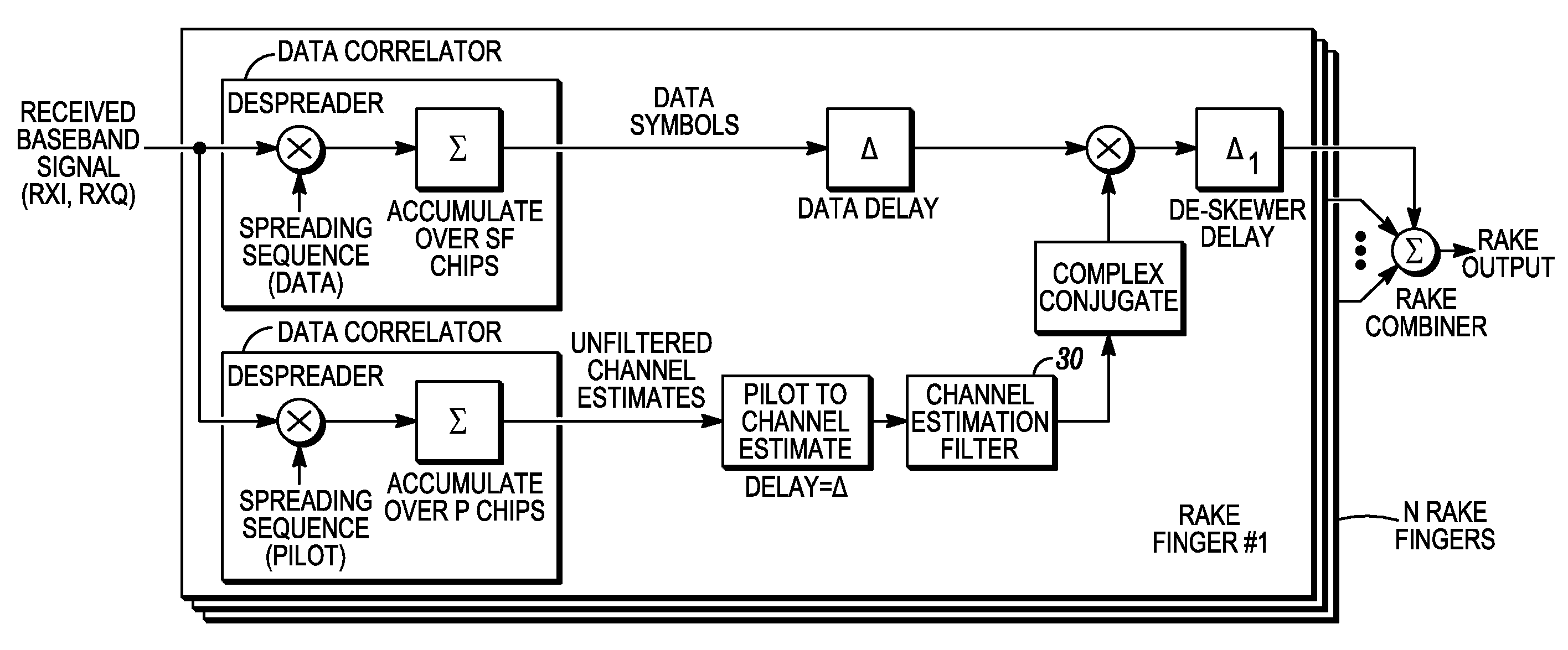
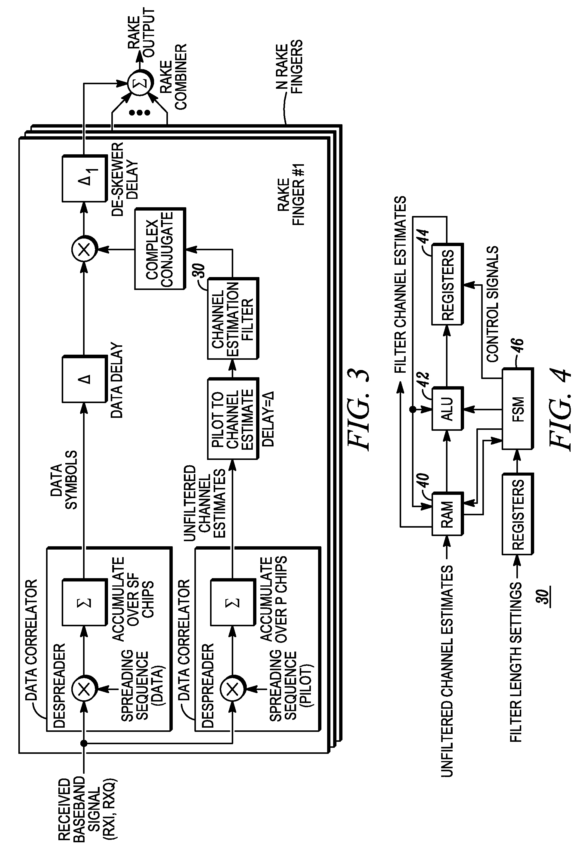
The present invention provides an improved method for channel estimation in a CDMA communication system that reduces computational complexity and integrated circuit size and cost without sacrificing performance. The method uses a pilot channel with a known pilot sequence to derive a phase reference for coherent demodulation. The pilot channel is also used for identifying the initial and delayed rays of communicating base stations, and for coherent demodulation of the communication channels. The method addresses the effects of noise and Doppler frequency shifts, and provides a more efficient solution for channel estimation in CDMA communication systems.

Problems solved by technology

However, changing the filter bandwidth would most likely cause one or more frame errors.
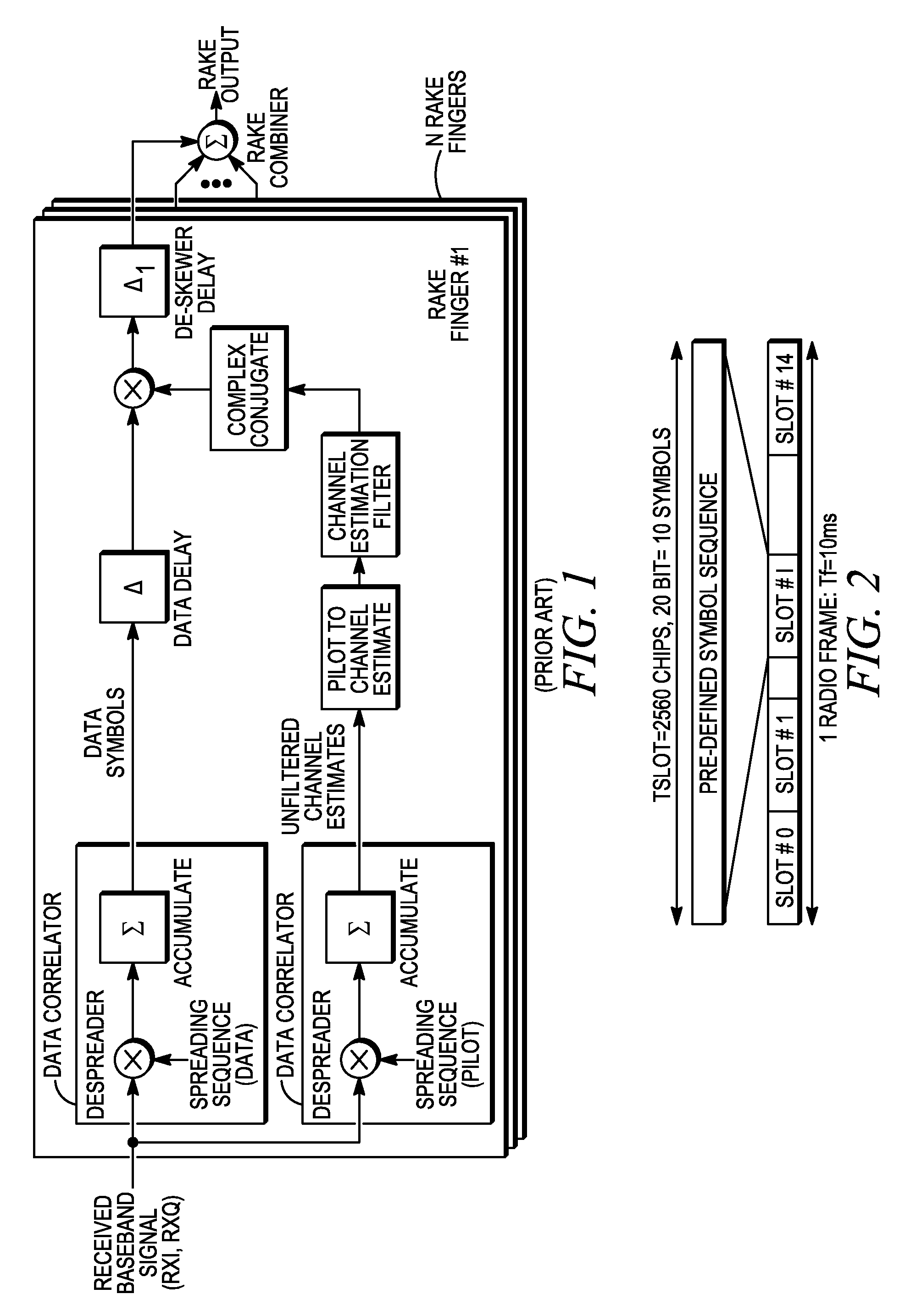
In addition, the delay buffer must be large enough to contain all possible delays that could be encountered, resulting in a very large delay buffer which is costly and takes up much area on an integrated circuit.
Moreover, it has been found that Doppler frequency shifts can also affect coherent reception which has not been addressed in the prior art.
Although there is a significant amount of prior art on using FIR filters for channel estimation, none of these have a filter length (channel bandwidth) that is varied as a function of Doppler rate.

Method used


Image

  • Channel estimation in a rake receiver of a CDMA communication system
  • Channel estimation in a rake receiver of a CDMA communication system
  • Channel estimation in a rake receiver of a CDMA communication system

Examples


example

[0030]It is known that if a single bandwidth channel estimation filter is used, there can be significant BER degradation at extreme Doppler rate and / or SNR conditions. A numerical simulation was performed using the finite-impulse-response channel estimation filter with fixed delay and dynamic bandwidth, in accordance with the present invention. The results are provided below. Simulation data, as is known in the industry, was used in the numerical simulation for all simulations. In particular, degradation was determined with respect to ideal channel estimation at a SFER=1%, Ior / Ioc=0 dB, flat fading channel and DPCH=12.2 kbps.

[0031]FIG. 6 shows a graph of the results indicating channel degradation (dB) versus Doppler shift due to the speed indicated. In the first column, tested at a speed of 1 km / h, a test was conducted using a filter of fixed seventeen taps (symbol length) versus the present invention wherein a filter length dynamically adjusted (asymmetrically) to seventy-three tap...


PUM


Abstract

A method and apparatus for channel estimation in a rake receiver of a CDMA communication system operates with a finite-impulse-response channel estimation filter with L taps and having a fixed delay. A pilot sequence of a received sequence of data from a channel of the communication system on the rake receiver is input. A quality of the channel of the communication system is determined using noise or Doppler measurements. These measurements are used in adjusting a bandwidth of the filter to accommodate the channel quality while keeping the fixed delay, which minimizes the delay buffer size. The filter is then used to operate on the received sequence of data to provide coherent modulation.

Description

FIELD OF THE INVENTION[0001]The present disclosure relates generally to wireless communications, and more particularly to channel estimating in wireless communications devices, for example, in a rake receiver of CDMA based user equipment, devices and methods.BACKGROUND OF THE INVENTION[0002]In a Code Division Multiple Access (CDMA) communication system, all base stations in all cells may use the same radio frequency for communication. Base stations are uniquely identified in the system by uniquely-assigned spreading codes. Two specified pseudorandom noise (PN) sequences of 215 bits length are used by all the base stations. In a quadrature modulated system, one sequence is used for the in-phase (I) channel spreading of the I channel symbols and the other is used for the quadrature (Q) channel spreading of the Q channel symbols. Mobile stations in the system possess the same two 215 bits length spreading codes and use them for the initial de-spread of the I and Q channels.[0003]The sy...

Claims


Application Information

Patent Timeline
Patent Type & Authority Patents(United States)
IPC IPC(8): H04B1/707H04L1/20H04L25/02
CPCH04L25/0228H04L1/20H04B1/7115H04B1/7117
Inventor ZANCHO, BRYAN W.LAROSA, CHRISTOPHER P.MALLETTE, ALEXANDREOLIVER, JOHN P.
Owner GOOGLE TECH HLDG LLC
Learn More