Method and apparatus for performing overhead crane rail alignment surveys

a technology of rail alignment and overhead crane, which is applied in the direction of runways, instruments, runways, etc., can solve the problems of crane skew, costly repair, wear and tear of rail and crane wheels, etc., and achieve the effect of improving the speed and accuracy of overhead crane rail survey and improving the safety of survey personnel

Inactive Publication Date: 2008-09-30
WICKHART JOHN C
View PDF23 Cites 15 Cited by
  • Summary
  • Abstract
  • Description
  • Claims
  • Application Information

AI Technical Summary

Benefits of technology

[0019]In one exemplary embodiment, a crane rail survey carriage is selectively pulled or pushed along an overhead crane rail by an overhead crane itself. Removable wheels on the rail survey carriage may be contoured to the shape and size of the railhead of the crane rail to keep the apparatus centered on the rail. A specially configured pivot arm, or driving arm, extending from the rail survey carriage to the rail sweep of the overhead crane end truck allows the rail survey carriage to remain plumb, as the crane selectively pushes or pulls the rail survey carriage along the crane rail, despite lateral movement of the crane. A prism, or sighting target, attached to a protruding arm are visible to a survey instrument operator on the ground. Three-dimensional coordinate data (e.g. XYZ coordinate data) may be recorded and used to generate an as-built profile of the rail that may be compared to rail alignment standards. From this data crane skew may also be measured. Accordingly, the advantages of the described method and device include: improved safety for survey personnel when performing overhead crane rail surveys, improved speed and accuracy of overhead crane rail surveys; improved data resulting from an overhead crane rail survey that may be used, not only to produce rail alignment profiles, but also rail elevation profiles, span profiles and to troubleshoot operational problems related to crane skew; as well as, electronically storable rail survey data that readily supports analysis of historic rail survey data to identify trends and potential problems before they occur. Further advantages will become apparent from a study of the following drawings and descriptions.

Problems solved by technology

Many types of rail surveys involve time-consuming methods that require the rail to be locked out (i.e., power to the hot rail turned off) and survey personnel to walk the length of the runway.
Imbalances in motor output to the respective end trucks can cause crane skew even though the crane rails themselves are within tolerance guidelines.
These imbalances result in wear on the rail and crane wheels, both of which are costly to repair.
This method, when used in conjunction with a tape measure to measure the span between crane rails, is not very accurate and is extremely time consuming.
With two exceptions, the prior art for rail surveying refers primarily to techniques for use on train tracks and elevation tracks which are not applicable for use with respect to overhead cranes.
Although the devices described in Waisanen and Pojda may be used to collect alignment information for a single crane rail, the systems suffer from serious deficiencies.
Such complex devices, mounted in the often harsh operational environment of some facilities, are likely to fail, resulting in lost operational capability, a need for specialized repairs, and, possibly, down-time for the crane itself.
Further, the devices described in Waisanen or Pojda are not capable of providing crane operators with sufficient information to quickly and accurately identify the root cause of misalignment problems within an overhead crane system.
Neither the Waisanen device nor the Pojda device is capable of providing information related to span alignment, or elevation.
Further, neither device is capable of providing timely information related to crane skew which may be used to identify and correct imbalances in the drive motors so as to avoid operating conditions in which the crane end truck wheels are not positioned parallel to the crane rails, and thereby avoid stresses that may result in misalignment of the respective crane rails, and wear to the crane rail and end truck wheels, all of which are costly to repair.

Method used


Image

  • Method and apparatus for performing overhead crane rail alignment surveys
  • Method and apparatus for performing overhead crane rail alignment surveys
  • Method and apparatus for performing overhead crane rail alignment surveys

Examples


Embodiment Construction

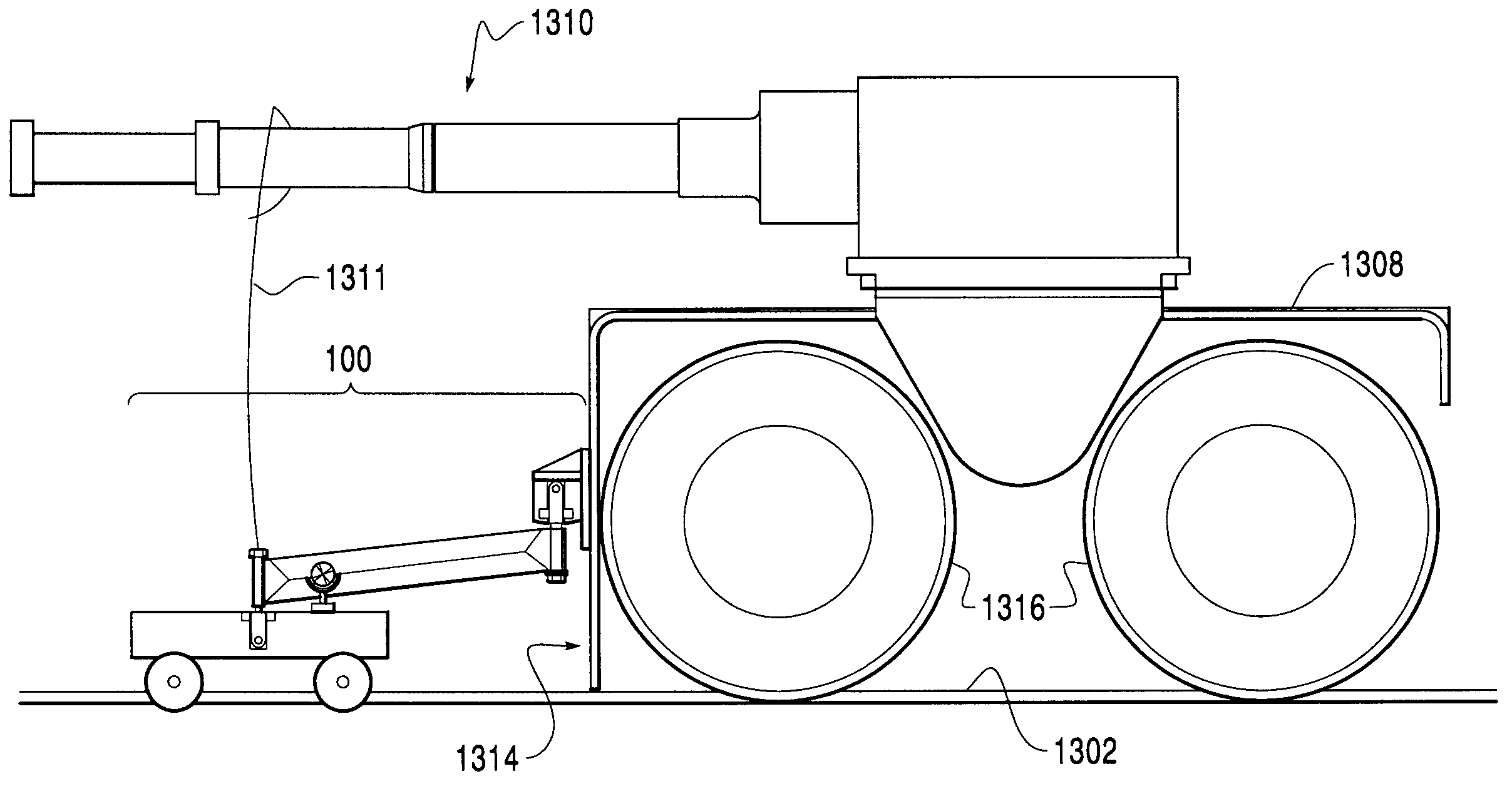
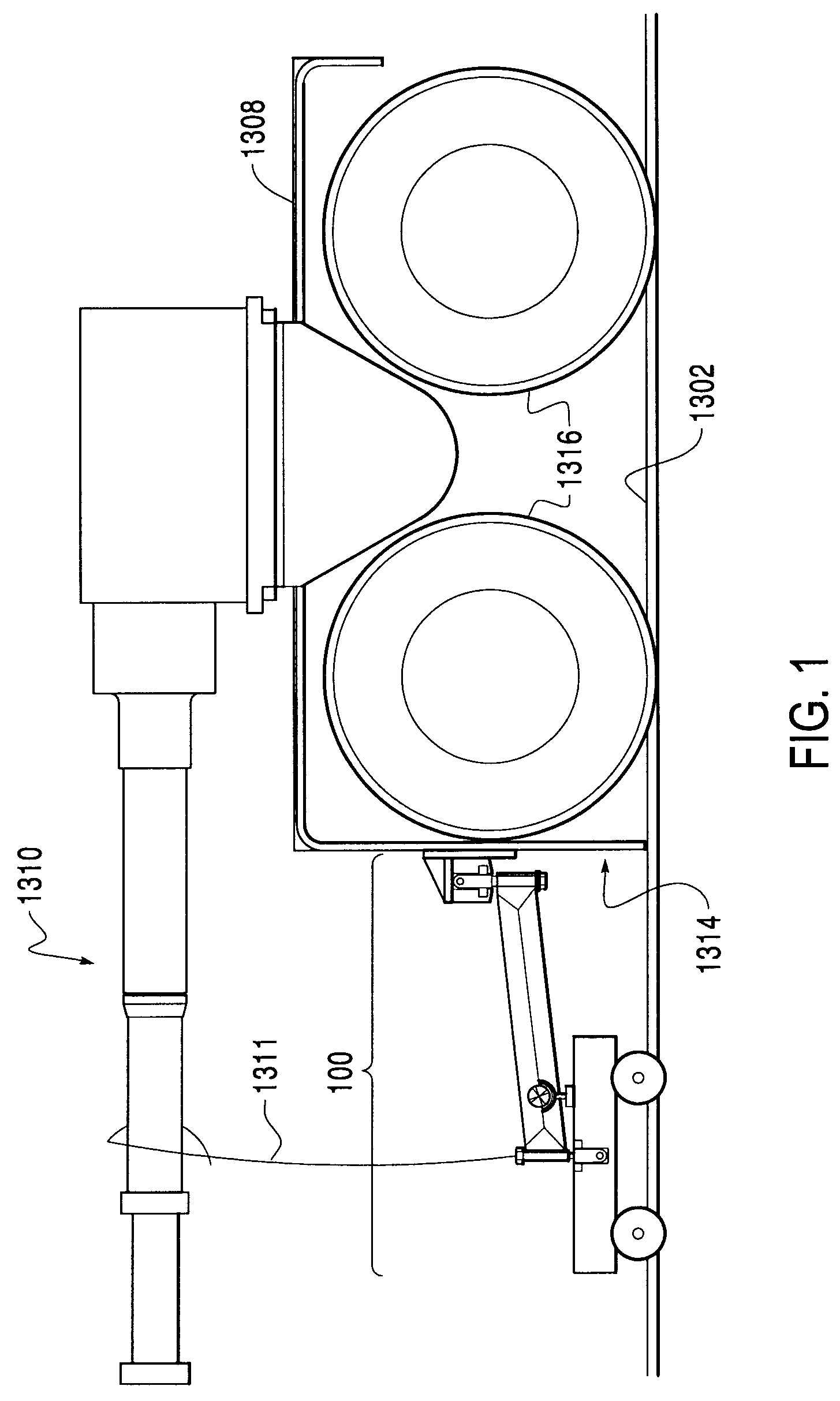
[0034]The described rail survey carriage may be used in surveying an overhead crane rail for straightness, span and elevation. Further, the survey information collected may be used to determine whether or not an overhead crane, per se, is skewed at any measurement point. Embodiments of the described rail survey carriage may be used in conjunction with a combination electronic transit (ET) / electronic distance measuring (EDM) device, or ET / EDM device, commonly referred to as a total station, positioned on the loading dock.

[0035]FIG. 12 is a view in schematic perspective of an exemplary portable ET / EDM device 1200 which may be used with exemplary embodiments of the described rail survey carriage described below with respect to FIGS. 1-8.

[0036]As shown in FIG. 12, ET / EDM device 1200 may include an electronic transit 1202, with electronic distance measuring capabilities, mounted on a tripod 1204, and an attached calculating device 1206 with a keypad 1208 and a display 1210.

[0037]An ET / ED...


PUM


Abstract

A method and apparatus for conducting an overhead crane runway system survey uses a survey apparatus that is alternately pushed or pulled by an overhead crane. The survey apparatus, having a wheeled carriage, includes survey sighting targets, e.g., prisms, that are visible to survey personnel on the ground. XYZ data is there collected and a rail alignment profile, a rail elevation profile, a rail span profile, and / or a crane skew profile may be generated. The data and profiles generated may reviewed to ascertain whether the overhead rails conform to alignment specifications. Further, crane skew data may be reviewed to determine whether the crane itself may be misaligned.

Description

CROSS-REFERENCE TO RELATED APPLICATION[0001]This application claims priority to U.S. Provisional Application No. 60 / 760,924 filed on Jan. 23, 2006, the disclosure of which, including all materials incorporated therein by reference, is incorporated herein by reference in its entirety.BACKGROUND[0002]1. Field of Invention[0003]This invention relates to surveying an existing overhead crane runway system to determine its straightness, span and elevation.[0004]2. Description of the Related Art[0005]An exemplary overhead crane, with which exemplary embodiments of the described rail survey carriage, or survey unit, and rail survey data collection methods may be used, is shown in FIG. 13. As shown in FIG. 13, such a traveling overhead crane 1300 may span a distance between two crane rails 1302, each crane rail supported by a crane girder 1304, and each crane girder supported by a plurality of support columns 1306.[0006]Overhead crane 1300 may contact each of crane rails 1302 with an end tru...

Claims


Application Information

Patent Timeline
Patent Type & Authority Patents(United States)
IPC IPC(8): G01B11/14B66C13/46
CPCB61K9/08B66C15/00B66C7/00
Inventor WICKHART, JOHN C
Owner WICKHART JOHN C
Why Eureka
Try Eureka