Optometric apparatus and lens power determination method

a technology of optometry and power determination, which is applied in the field of optometric equipment and lens power determination, can solve the problems of difficult eyeglasses or contact lenses at home or in shops, and requires expert knowledge to operate, and achieves the effect of accurate eye examination

Inactive Publication Date: 2008-09-30
VISION MEGANEKK
View PDF11 Cites 20 Cited by
  • Summary
  • Abstract
  • Description
  • Claims
  • Application Information

AI Technical Summary

Benefits of technology

[0011]In order to overcome the problems described above, preferred embodiments of the present invention provide an optometric apparatus and a lens power determination method which can perform accurate eye examinations on those who have astigmatism, myopia, and hyperopia and a wide range of refractive powers, and which can also be applied particularly to those with mixed astigmatism.

Problems solved by technology

However, such an auto-refractometer is very expensive and requires expert knowledge to operate.
Thus, it was difficult to order eyeglasses or contact lenses at shops or at home where no such facilities were available.
Thus, the difference between myopia and hyperopia cannot be distinguished, which may provide misleading eye examination results.
Thus, it is difficult to distinguish between hyperopia and myopia using only the test symbols for determining visual acuity.
Furthermore, although some subjects with astigmatism may have mixed astigmatism which causes one of the major and minor axes to exhibit myopia and the other to exhibit hyperopia, the conventional optometric device cannot be applied to these subjects.

Method used


Image

  • Optometric apparatus and lens power determination method
  • Optometric apparatus and lens power determination method
  • Optometric apparatus and lens power determination method

Examples


Embodiment Construction

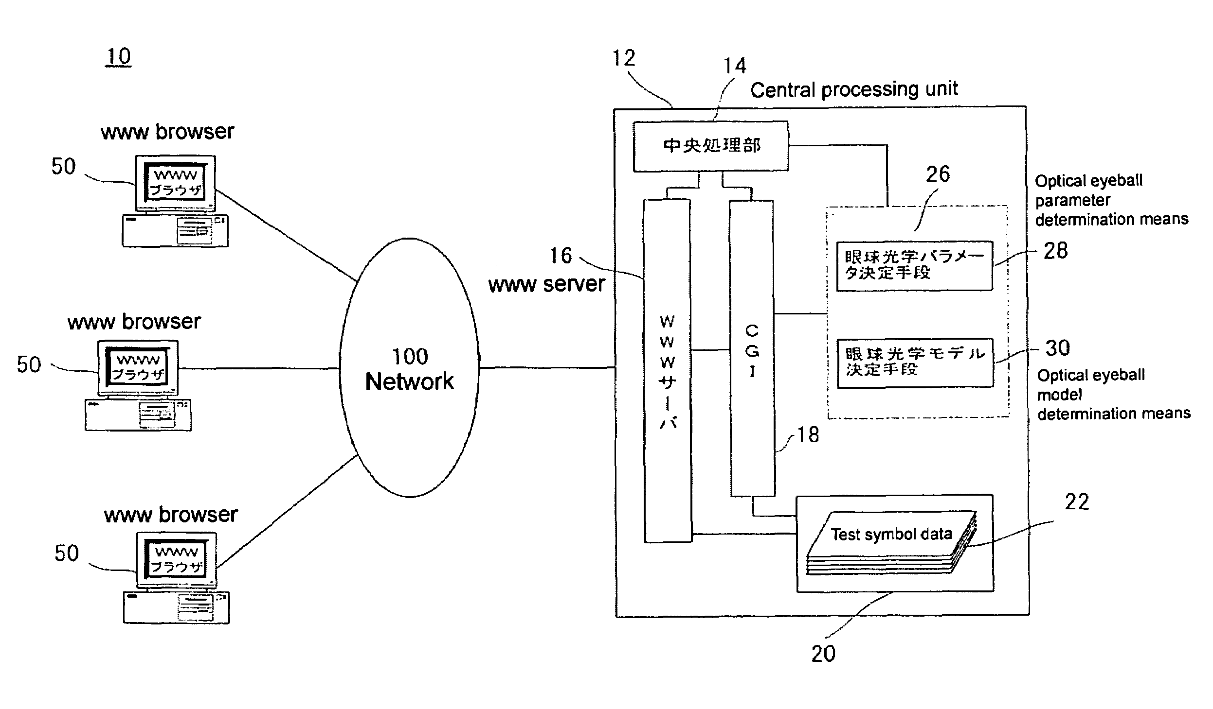
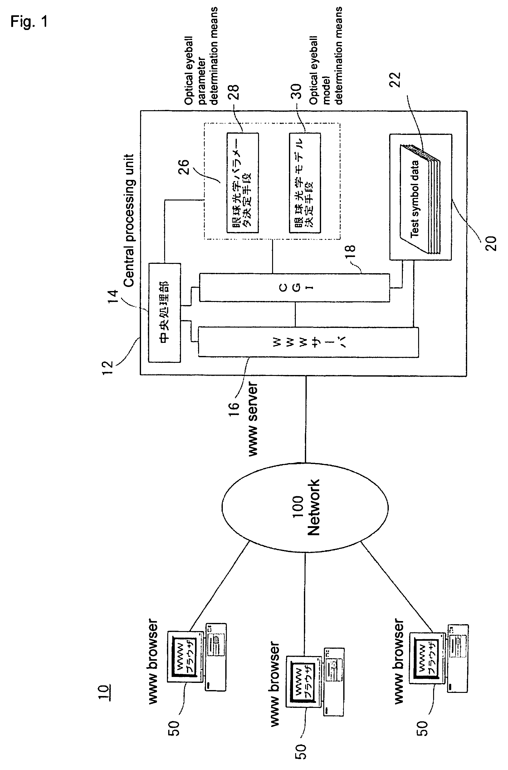
[0158]FIG. 1 is a system configuration of an optometric apparatus according to a preferred embodiment of the present invention. As shown, an optometric apparatus 10 includes an eye examination server 12, a subject terminal 50, and a network 100.

[0159]The eye examination server 12 provides data such as test symbol data to the subject terminal 50, and determines astigmatic axes, hyperopia or myopia, and refractive powers of subjects based on results entered on the subject terminal 50, thereby performing subjective eye examinations. As the hardware for the eye examination server 12, computers such as personal computers, workstations, or servers are provided. The eye examination server 12 can have various applications installed therein to thereby provide various services. The eye examination server 12 also includes a modem or network interface card (not shown) for two-way communications with the subject terminal 50 via the network 100.

[0160]The eye examination server 12 includes a centr...


PUM


Abstract

An optometric apparatus and an optometric method which perform an accurate eye examination on people who have a wide range of refractive powers with astigmatism, myopia or hyperopia, and which are also applicable especially to those with mixed astigmatism are provided. The apparatus performs a subjective eye examination by prompting a subject to view test symbols displayed on a computer screen by one of the right and left eyes at a time. The system includes astigmatic axis angle determination means which displays test symbols for determining an astigmatic axis angle and then determines the astigmatic axis angle, hyperopia and myopia determination means which displays test symbols for determining hyperopia or myopia in two orthogonal orientations selected based on the determined astigmatic axis angle, and determines hyperopia or myopia at the astigmatic axis angle and at an angle orthogonal thereto, and refractive power determination means which displays test symbols for determining a refractive power in two orthogonal orientations selected based on the determined astigmatic axis angle and determines a refractive power at the astigmatic axis angle and at an angle orthogonal thereto.

Description

BACKGROUND OF THE INVENTION[0001]1. Field of the Invention[0002]The present invention relates to an optometric apparatus and a lens power determination method to perform a subjective eye examination by prompting a subject to view test symbols displayed on a display means using one of the right and left eyes at a time. More particularly, the present invention relates to an optometric apparatus and a lens power determination method which are suitable for eye examinations performed to determine lens powers, e.g., in order to sell eyeglasses or contact lenses over the Internet.[0003]2. Description of the Related Art[0004]Conventionally, to determine the refractive power of eyeglasses or contact lenses, a conventional method used an auto-refractometer to objectively determine the refractive coefficient of the eyeball and then the subject actually wore ready-made corrective lenses in order to test the subject's visual acuity.[0005]However, such an auto-refractometer is very expensive and ...

Claims


Application Information

Patent Timeline
Patent Type & Authority Patents(United States)
IPC IPC(8): A61B3/02A61B3/00A61B3/032A61B3/036
CPCA61B3/036A61B3/032
Inventor TOSHIMA, AKIOYOSHIDA, TAKEHIKO
Owner VISION MEGANEKK
Why Eureka
Try Eureka