In-situ detection method for stray light in step scan projection mask aligner

A step-scanning and in-situ detection technology, which is applied in microlithography exposure equipment, machine/structural component testing, optical instrument testing, etc., can solve problems such as the inability to distinguish the source of stray light, eliminate stray light, and improve measurement efficiency effect

Active Publication Date: 2005-08-17
SHANGHAI MICRO ELECTRONICS EQUIP (GRP) CO LTD
View PDF1 Cites 26 Cited by
  • Summary
  • Abstract
  • Description
  • Claims
  • Application Information

AI Technical Summary

Problems solved by technology

[0006] The purpose of the present invention is to provide an in-situ detection method of stray light in a step-and-scan projection lithography machine, which mainly solves the technical problem that the existing methods can only measure the size of the stray light and cannot distinguish the source of the stray light. Compared with t

Method used


Image

  • In-situ detection method for stray light in step scan projection mask aligner
  • In-situ detection method for stray light in step scan projection mask aligner
  • In-situ detection method for stray light in step scan projection mask aligner

Examples


Embodiment Construction

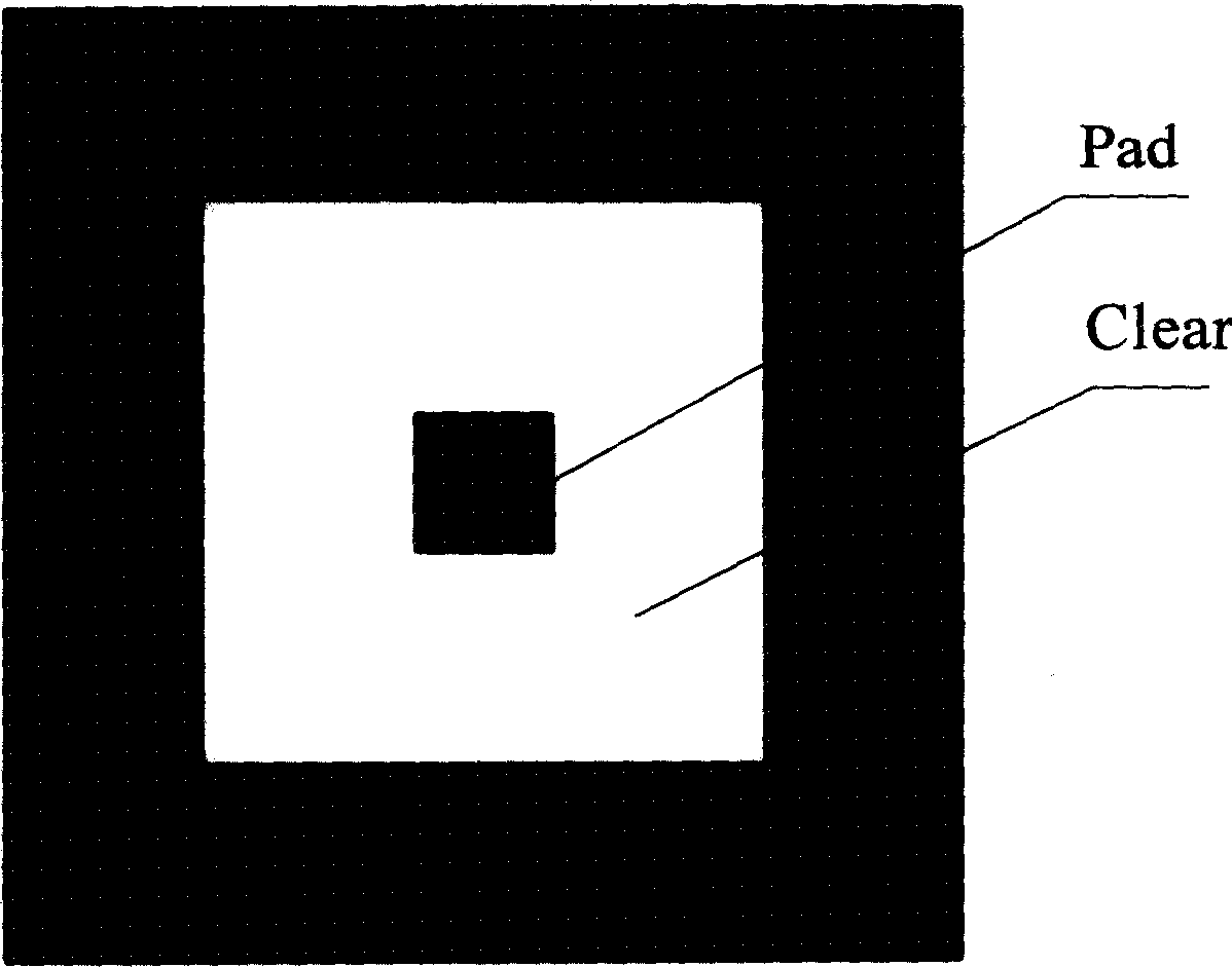
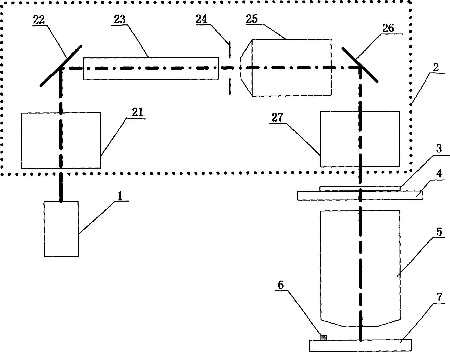
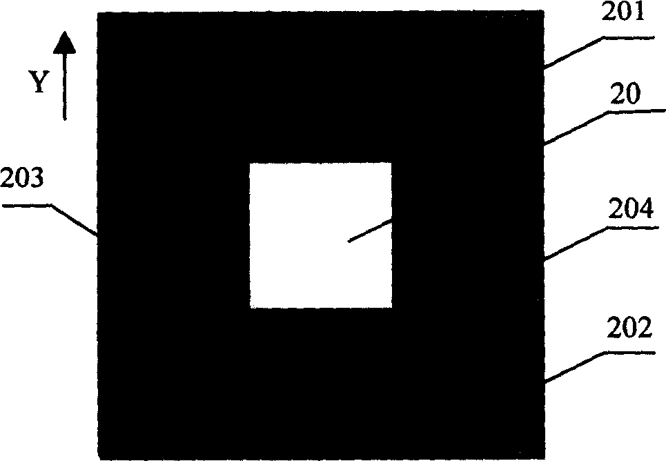
[0032] The invention provides an in-situ detection method for stray light in a step-scan projection lithography machine, which can not only measure the size of the stray light, but also analyze the source of the stray light, providing a basis for taking targeted measures to eliminate the stray light in accordance with. The system structure used by the method is as follows figure 2 As shown, it includes: a light source 1 for generating a projected light beam; an illumination system 2 capable of adjusting the light intensity distribution and partial coherence factor of the light beam emitted by the light source 1; a mask 3; a mask capable of carrying the mask 3 and precisely positioned A mold stage 4; a projection objective lens 5 for imaging the mask 3 and whose numerical aperture is adjustable; a workpiece stage 7 capable of carrying silicon wafers and capable of precise positioning, and an energy sensor 6 arranged on the workpiece stage 7.

[0033] The lighting system 2 mai...


PUM


Abstract

This invention relates to an in-situ test method for stray light in a step scan projection aligner, which limits a spot on an object face by accurately positioning four slit blades and images on a working platform by a projecting object lens. An energy sensor tests that the light intensity at the spot photo center is Lo and finishes testing to MXN spots then to open the slit, the light intensity of above mentioned point light intensity is measured to be l, the stray light coefficient is computed by formula (1, -10)/10, if the stray light exceeds the required target of the exposure system, it analyses source of stray light. A special mask and two slit blades limit a spot imaged by projection object lens, an energy sensor tests light intensity distribution in the image spot to analyze if the stray light is from the illumination system or the project object lens.

Description

technical field [0001] The invention relates to an in-situ detection method of stray light in a projection lithography machine, in particular to an in-situ detection method of stray light in a step-and-scan projection lithography machine. Background technique [0002] The development of semiconductor technology requires the integration of semiconductor components to be higher and higher, and its circuit patterns to be more and more miniaturized. In order to improve the resolution of lithography, the projection objective lens of the lithography machine has become a diffraction-limited optical system, which puts forward high requirements on the performance of projection exposure. As we all know, the image surface of an optical imaging system usually receives not only imaging light, but also non-imaging light. The non-imaging light that reaches the image surface of the optical system is stray light. The presence of stray light reduces imaging contrast. Stray light is mainly c...

Claims


Application Information

Patent Timeline
IPC IPC(8): G01M11/00G03F7/20
Inventor 郭立萍王向朝
Owner SHANGHAI MICRO ELECTRONICS EQUIP (GRP) CO LTD
Why Eureka
Try Eureka