
Articulated ankle foot brace having a malleolar window

a technology of malleolar window and ankle brace, which is applied in the field of ankle brace, can solve the problems of restricting the plantarflexion/dorsiflexion movement of the ankle, challenging orthotic treatment of medial instability, and often only partially correctable conditions, and achieves the effect of reducing the tendency to have localized pressur

Active Publication Date: 2008-09-30
ENGELMAN IAN
View PDF8 Cites 15 Cited by
  • Summary
  • Abstract
  • Description
  • Claims
  • Application Information

AI Technical Summary

Benefits of technology

[0013]It is an object of the present invention to resolve the shortcomings described above. In addition to the other various aspects of the invention, it uses many available areas for corrective applied force. Having more support area reduces the tendency to have localized pressure by spreading the pressure out over a greater area.
[0016]Different aspects of the invention use a unique system and approach which provides correction more effectively and more comfortably than existing solutions. The invention maximizes the use of available areas for applying corrective forces, and thus reduces the tendency to have localized pressure by spreading the pressure out over a greater area.

Problems solved by technology

The orthotic treatment for Medial instability is challenging.
As the body weight exerts strong forces which need to be controlled, the condition is often only partially correctable.
Some existing solutions provide support for the foot and ankle, but lack an articulation, therefore restricting the plantarflexion / dorsiflexion movement of the ankle.
Other articulated designs commonly have tolerance issues with pressure on the lateral malleolus or don't recruit the benefits of stability one can get from controlling this part of the foot and ankle.
This misunderstood need to locate the articulation near the malleoli has resulted in the forfeit of a strategic and effective area of control.
Furthermore, an orthosis takes a lot of room in the shoe and often the user of orthopedic braces faces difficulty finding shoes that are big enough to accommodate the brace and foot combination.
However, most brace designs to date avoid movement control of the medial malleolus, because of general lack of supporting soft tissue over this bony prominence.
The lack of soft tissue makes the medial malleolus intolerant of high corrective pressures.

Method used


Image

  • Articulated ankle foot brace having a malleolar window
  • Articulated ankle foot brace having a malleolar window
  • Articulated ankle foot brace having a malleolar window

Examples


Embodiment Construction

[0030]The following embodiments will be described in details by way of guidance and example to assist the skilled person in implementing certain aspects of the invention.

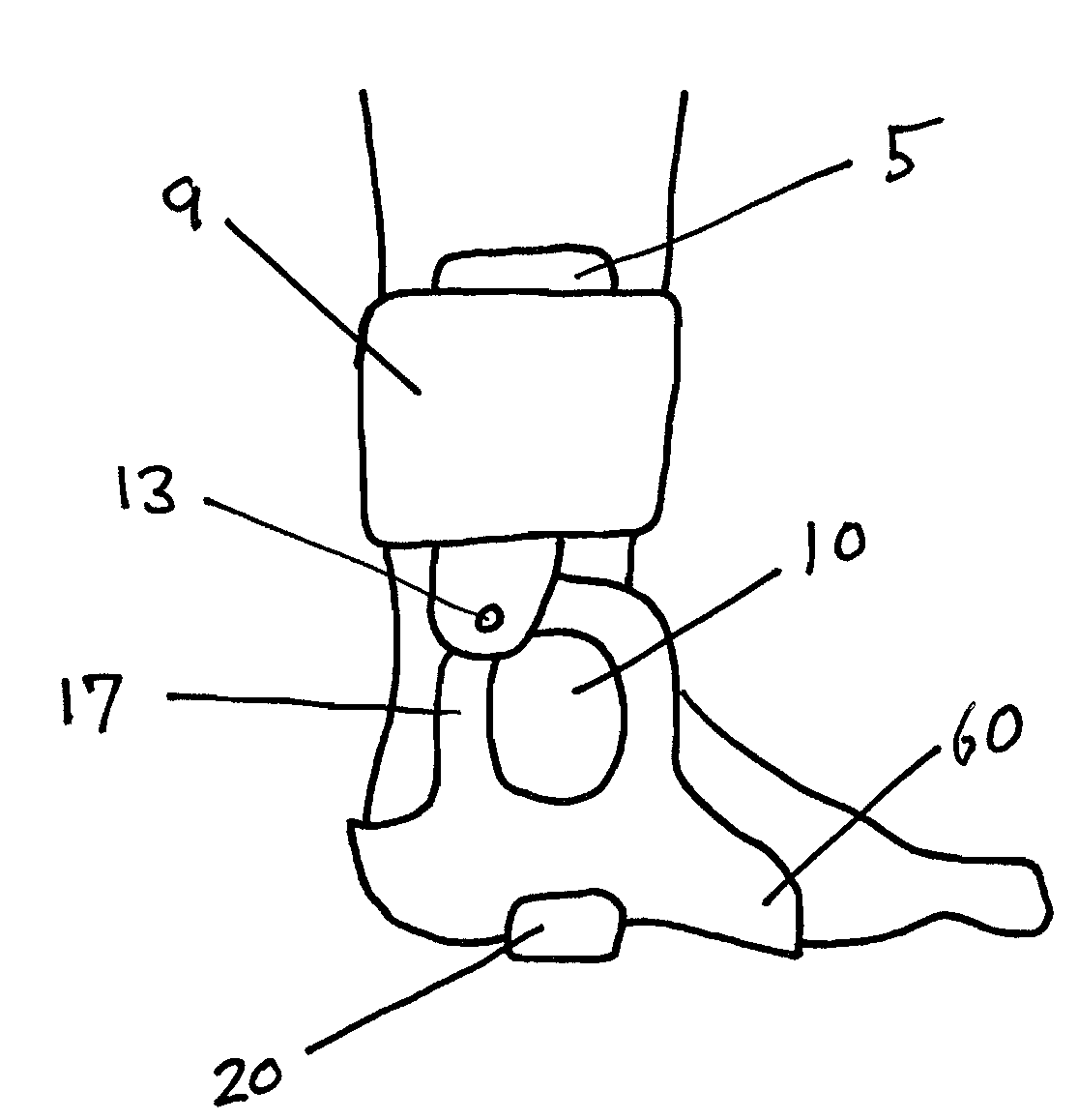
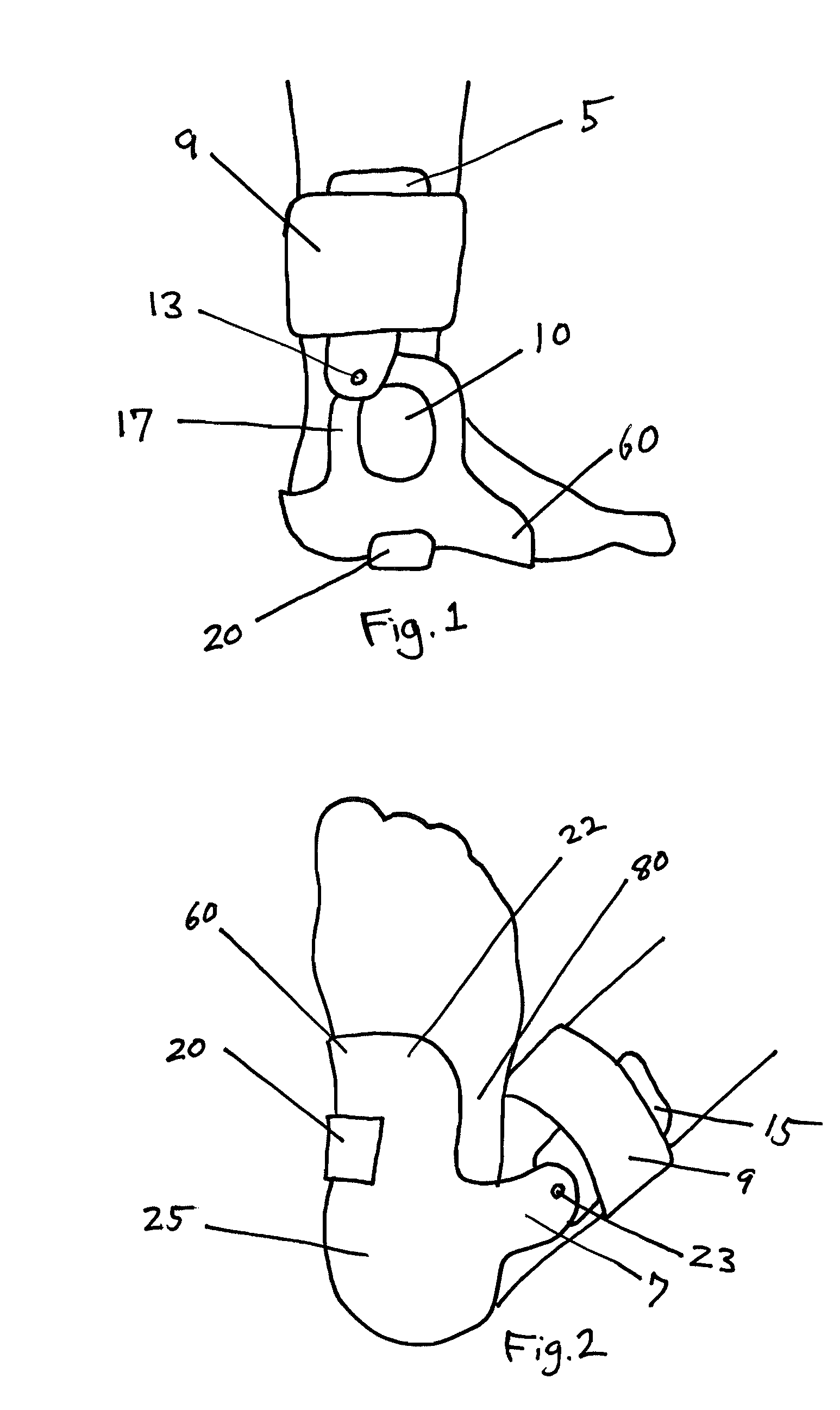
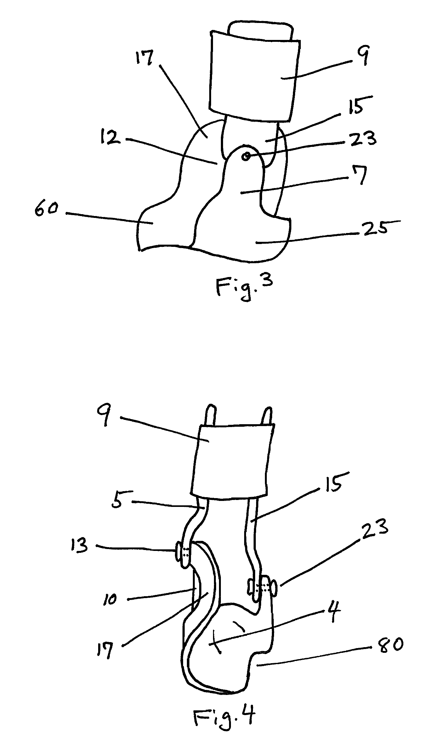
[0031]As will be clear to the skilled in the art, an ankle brace requires a heel stirrup 25 with horizontal bottom section and upwardly extending lateral lower upright 7 and medial lower upright 17. Common brace designs further utilize upper medial 5 and upper lateral 15 uprights, hinged respectively to the lower medial and lateral uprights. The combination of the respective lower and the upper uprights may be considered, and are so termed herein, as a vertical wall of the brace.

[0032]For clarity, the following will describe a brace design directed to assisting patients suffering from medial instability. The skilled in the art will recognize that for treating lateral instability the description made herein needs to reversed, i.e. the description of the medial uprights should be replaced by the lateral uprights, and ...


PUM


Abstract

An ankle foot brace having a heel stirrup, a lower lateral and medial uprights, and an upper lateral and medial uprights hinged to the respective lower uprights. A malleolar window, preferably with a membrane extending thereupon, creates a hammock like support for the malleolus. The hinge point on the side having the malleolar window is moved upwards and preferably back from the apex of the malleolus. Doing so allows the application of tolerable corrective forces at this location to help prevent undesired movement of the malleolus. If a membrane is not employed, the window allows application of corrective forces in the vicinity of the malleolus without causing pain thereto.

Description

FIELD OF THE INVENTION[0001]This invention relates generally to a brace, and more particularly to an ankle foot brace having a malleolar window.BACKGROUND OF THE INVENTION[0002]To assist in understanding the present invention and its various aspects, these specifications and their attached claims will refer to certain geometrical terms such as up, down, horizontal and vertical, forward and backward. The reference point to such geometrical directions should be taken to be a human foot. Thus for example, the term forward should be construed as extending from the heel substantially in the general direction of the toes, and backward refers generally to the opposite direction. Similarly the term horizontal should be construed as the general plane on which normal foot at rest, and planes parallel thereto, with the heel defining a reference plane commonly referred to as bottom. Similarly the term vertical extends at or about 90 degrees to the horizontal plane, and upward or downward to dir...

Claims


Application Information

Patent Timeline
Patent Type & Authority Patents(United States)
IPC IPC(8): A61F13/00
CPCA61F13/06
Inventor ENGELMAN, IAN
Owner ENGELMAN IAN
Learn More