
Planar patch-clamp cartridge with integrated electrode

a cartridge and integrated technology, applied in the field of patch-clamp recording, can solve the problems of increasing reliability and reducing the cost of instruments, and achieve the effect of improving the recording conditions of successive measurements

Inactive Publication Date: 2008-09-30
MOLECULAR DEVICES
View PDF4 Cites 16 Cited by
  • Summary
  • Abstract
  • Description
  • Claims
  • Application Information

AI Technical Summary

Benefits of technology

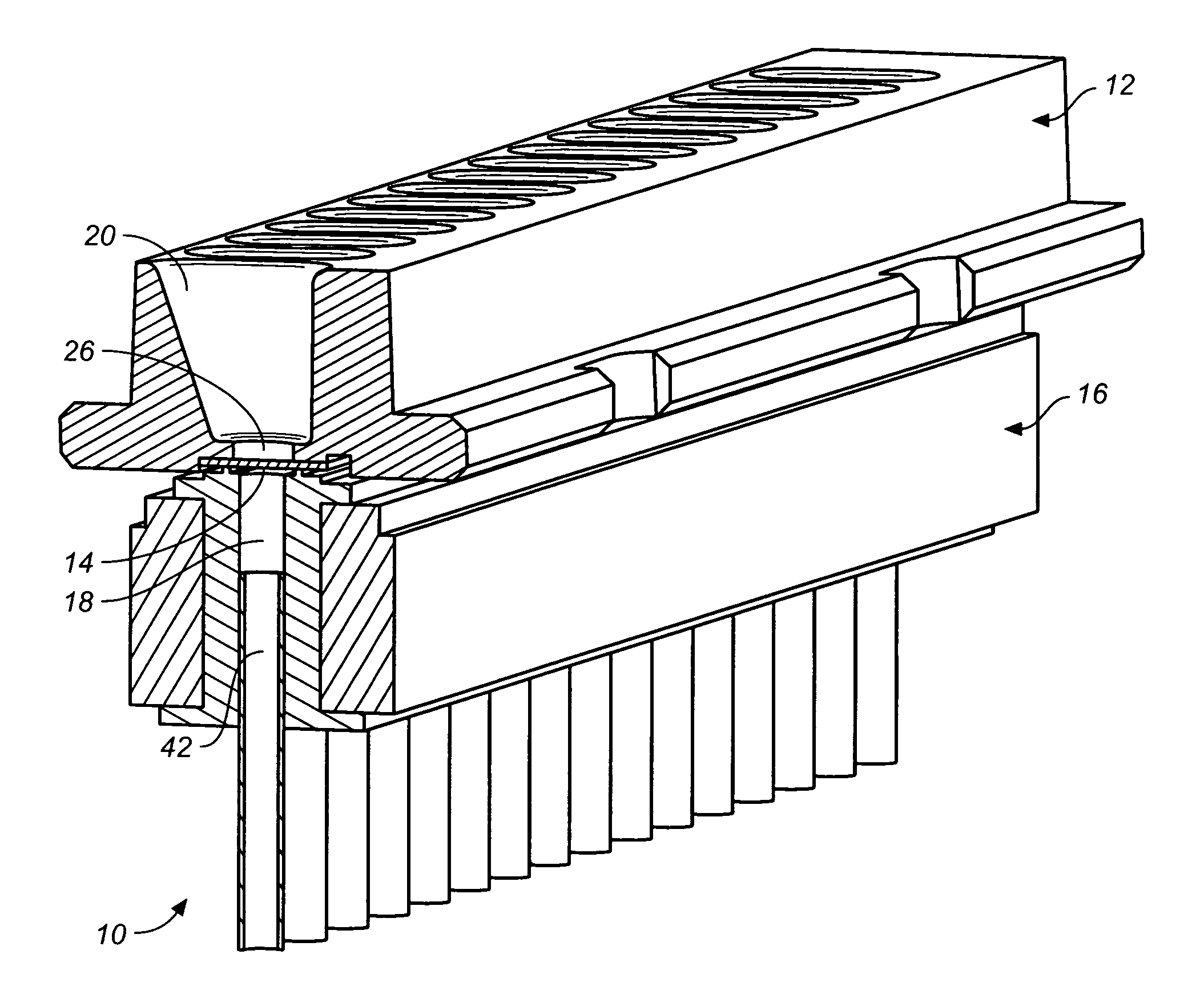
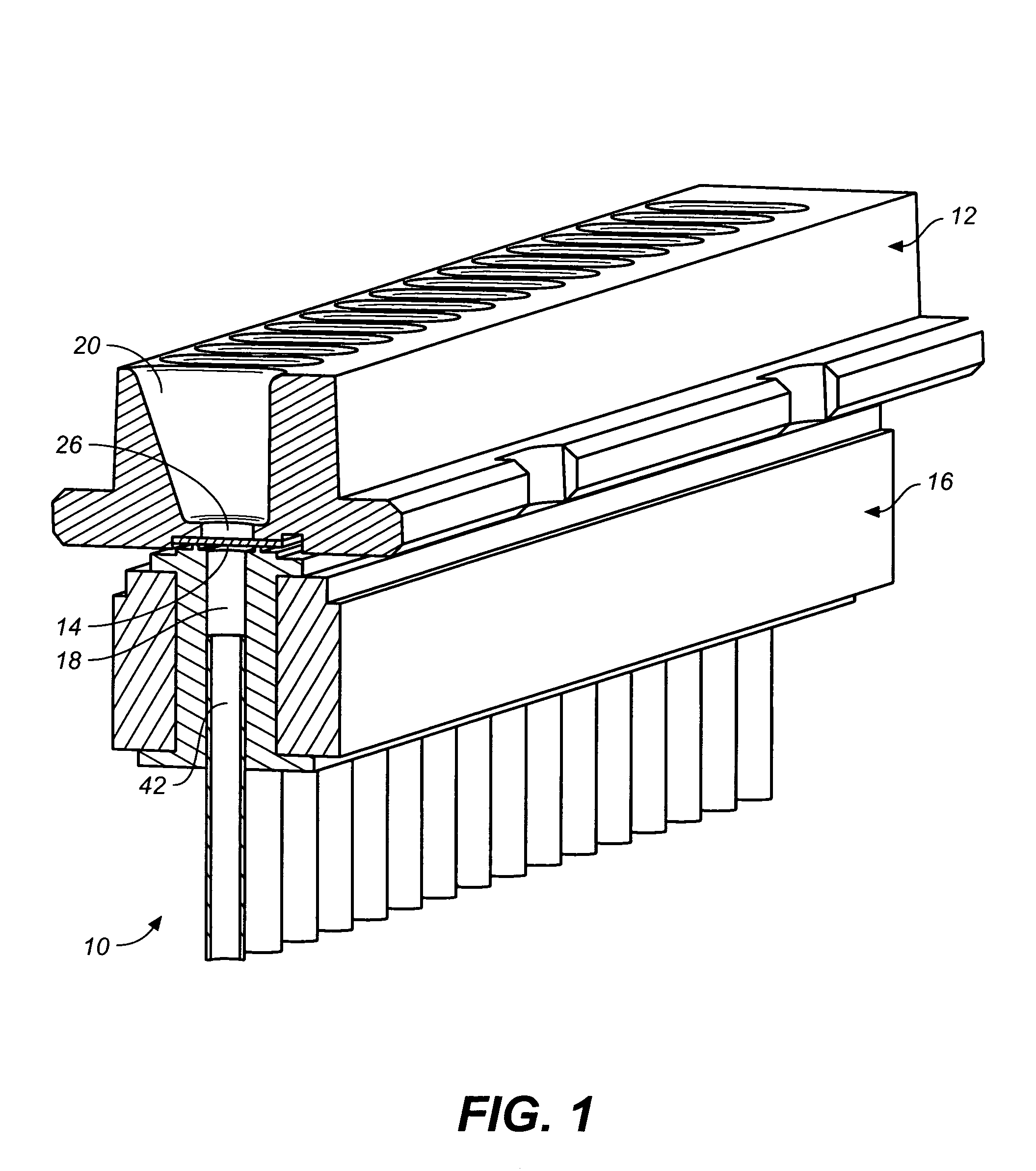
[0019]According to one aspect of the invention, one or both of the electrodes used to carry out planar patch-clamp recording are embedded or integrated into the cartridge, thus reducing the need for automatic positioning of the electrodes. Such simplification increases reliability and decreases the cost of the instrument. A common ground electrode is provided through a conductive medium reaching into each extracellular chamber from the bottom port of the chamber and extending to ground through the bottom of the cartridge's extracellular component. Various conductive media are disclosed, such as a silver layer coated with silver chloride, a silver wire, a silver wire coated with gold, a silver wire coated with a semipermeable layer, and a conductive-gel bridge.
[0020]According to another aspect of the invention, a method of solution delivery is disclosed wherein the planar patch-clamp cartridge is first primed with intracellular solution injected into each intracellular chamber from a dispensing tip that is removably inserted into the chamber from above, and then the cartridge is flipped over through a 180-degree arc of rotation. As a result, the intracellular chambers assume a face-down position, while the extracellular chambers on the opposite side are positioned face up. It was found that the intracellular solution is advantageously held in the chambers by surface tension, so that the cartridge can remain so positioned during recording. Because of the corresponding face-up position of the extracellular chambers, the same dispensing tips can also be used to provide extracellular solutions to the extracellular chambers.
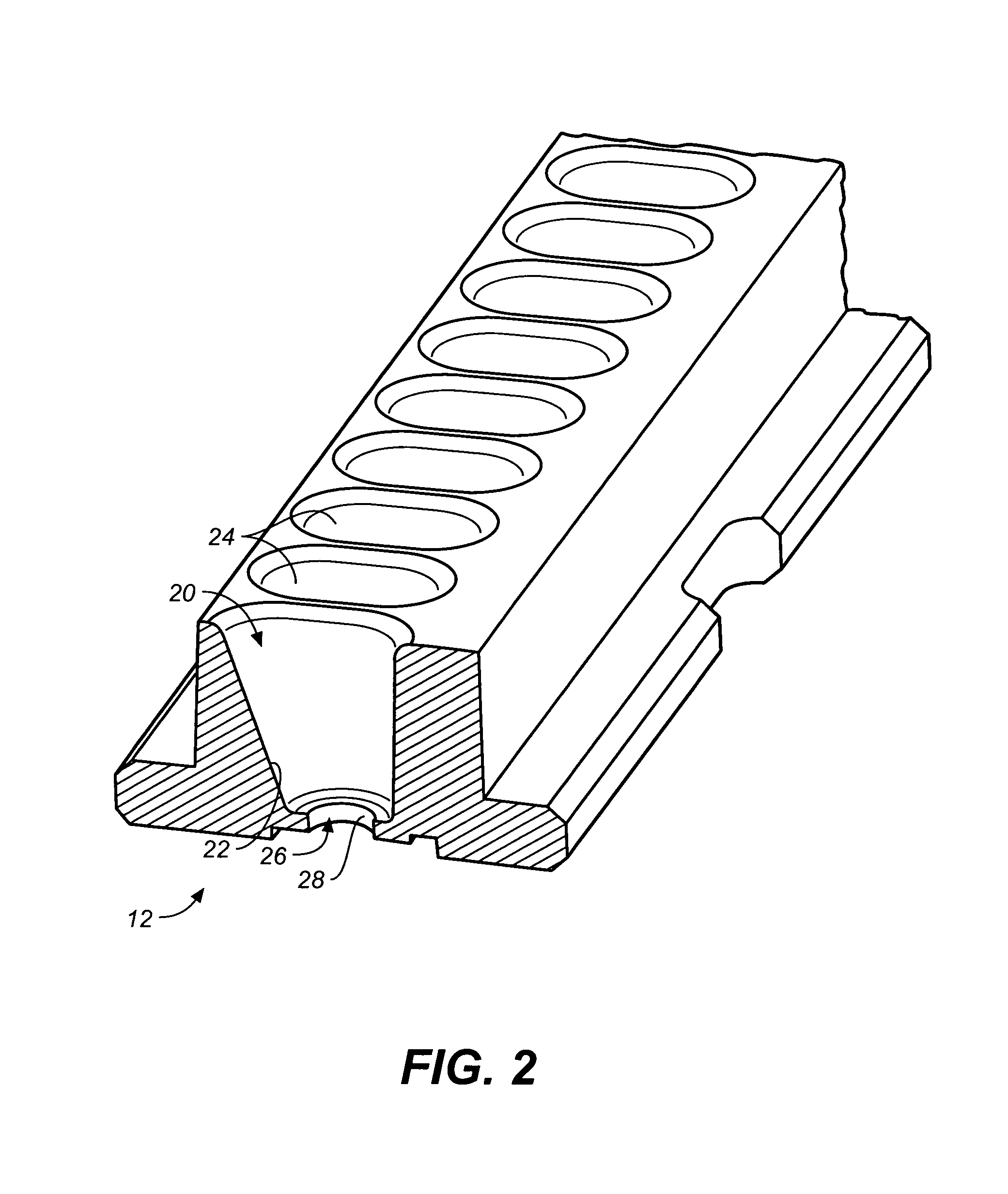
[0022]According to still another aspect of the invention, each extracellular chamber is provided with a sloped wall and the dispensing tip is positioned in contact with the sloped wall prior to the release of solution. Because of the resulting approximately tangential flow of solution along that wall, it was found that the process of exchanging fluids near the bottom of the extracellular chamber is materially improved. Accordingly, the recording conditions of successive measurements are also improved.

Problems solved by technology

Such simplification increases reliability and decreases the cost of the instrument.

Method used


Image

  • Planar patch-clamp cartridge with integrated electrode
  • Planar patch-clamp cartridge with integrated electrode
  • Planar patch-clamp cartridge with integrated electrode

Examples


Embodiment Construction

[0041]As used herein, the terms “intracellular” and “extracellular” refer to the two opposite sides of a patch-clamp aperture, typically defined by corresponding chambers adapted to receive fluids and test material. In particular, intracellular and extracellular fluids or solutions are intended to refer to any fluid dispensed to such opposite sides of the aperture, rather than being limited strictly to intracellular and extracellular solutions as these are technically defined in the art. Referring to the figures, wherein the same reference numerals and symbols are used throughout for like parts, FIG. 2 is an exemplary extracellular component 12 of a patch-clamp cartridge 10 according to the invention. The extracellular component 12 contains a number of extracellular chambers 20 (also referred to in the art as wells). Each chamber 20 has a top opening 24 several millimeters in diameter and a bottom port 26. Each chamber has at least one slanted wall 22 positioned at an angle with res...


PUM

PropertyMeasurementUnit
Angleaaaaaaaaaa
Electrical conductivityaaaaaaaaaa
Electrical conductoraaaaaaaaaa

Abstract

A planar patch-clamp cartridge includes a common ground electrode through a conductive medium reaching into each extracellular chamber. The cartridge is first primed with intracellular solution injected from dispensing tips inserted from above into the intracellular chambers. Then the cartridge is rotated 180 degrees, whereby the intracellular and extracellular chambers assume face-down and face-up positions, respectively. Extracellular solution is then delivered using the same dispensing unit. A plurality of silver tubes engages the intracellular chambers at the end of the rotation to provide electrical conductivity and suction to the intracellular chambers.

Description

RELATED APPLICATIONS[0001]This application is based on U.S. Provisional Ser. No. 60 / 423,245, filed Nov. 1, 2002, and is a continuation-in-part application of Ser. No. 09 / 973,388 filed Oct. 9, 2001, issued as U.S. Pat. No. 6,776,896.BACKGROUND OF THE INVENTION[0002]1. Field of the Invention[0003]This invention relates in general to the field of patch-clamp recording and, in particular, to a cartridge system with integrated electrodes suitable for measurements in automated, repeatable, parallel experiments.[0004]2. Description of the Related Art[0005]Conventional voltage clamping techniques used to conduct electrophysiological tests on a membrane assess electrical activity on the membrane by measuring current or voltage changes produced in response to exposure to various test stimuli. Typically, the membrane is pierced with two microelectrodes connected to an amplifier capable of recording current or voltage variations in response to stimuli such as voltage step changes, the applicati...

Claims


Application Information

Patent Timeline
IPC IPC(8): G01N33/487
CPCG01N33/48728C12M1/3407
Inventor OSIPCHUK, YURI
Owner MOLECULAR DEVICES
Learn More