Circuit and method for demodulating a servo position burst

a technology of position burst and circuit, which is applied in the field of electronic circuits, can solve the problems of incorrect position of the head-position circuit, inaccurate calculation of the burst amplitude, and inability to accurately calculate etc., and achieves the effect of shortening the position burst, calculating the burst magnitude and the head-position error signal more accurately

Inactive Publication Date: 2008-09-30
STMICROELECTRONICS SRL
View PDF18 Cites 9 Cited by
  • Summary
  • Abstract
  • Description
  • Claims
  • Application Information

AI Technical Summary

Benefits of technology

[0022]By using an algorithm that does not require heavy over sampling—for purposes of this application, heavy over sampling is a sampling rate more than four samples per cycle—and that is independent of the level of synchronization between the sample clock and the position bursts, such a circuit often allows shorter position bursts than a heavy-over-sampling circuit allows and calculates the burst magnitudes and the head-position-error signal more accurately than a circuit that uses a timing-dependent algorithm.

Problems solved by technology

Unfortunately, as discussed in more detail below in conjunction with FIGS. 1–5, increasing the density of the servo data, and thus increasing the frequency of the servo signal, may cause a disk drive's head-position circuit to improperly position the read-write head over a selected data track.
But if the frequency of the servo signal is too high, the servo circuit may be unable to generate enough samples for over sampling or maintain synchronization between the sample clock and the servo burst, and thus may calculate inaccurate values for the burst amplitudes.
Consequently, these inaccurate values may cause the disk drive to calculate an erroneous value for the head-position error signal, and thus may cause the head-position circuit to improperly position the head over the selected data track.
Unfortunately, by the time that the head 14 is over the position-burst sections 50A–50D (FIG. 4), phenomena such as noise and disk jitter may cause the edges of the sample clock to become offset from the peaks and zero crossings of the burst sinusoid.
Unfortunately, the lack of synchronization between the sample clock and the burst sinusoid may cause the head-position circuit (not shown in FIG. 5) to improperly position the head 14 over the selected track 22 (FIG. 4) during the fine positioning of the head.
But if the clock and burst sinusoid are imperfectly aligned as shown, then, ignoring noise and jitter, this algorithm yields an incorrect burst magnitude Y cos α instead of the correct burst magnitude Y. This incorrect burst magnitude may cause the disk drive 10 to calculate an inacccurate position-error signal, which may cause the motor 18 (FIG. 1) to move the head 14 to an undesired position.
Unfortunately, although heavily oversampling allows one to calculate the burst amplitude Y with an unsynchronized sampling clock, it typically requires more disk space due to the above-described lengthening of the position bursts 50A–50D (FIG. 4).

Method used


Image

  • Circuit and method for demodulating a servo position burst
  • Circuit and method for demodulating a servo position burst
  • Circuit and method for demodulating a servo position burst

Examples


Embodiment Construction

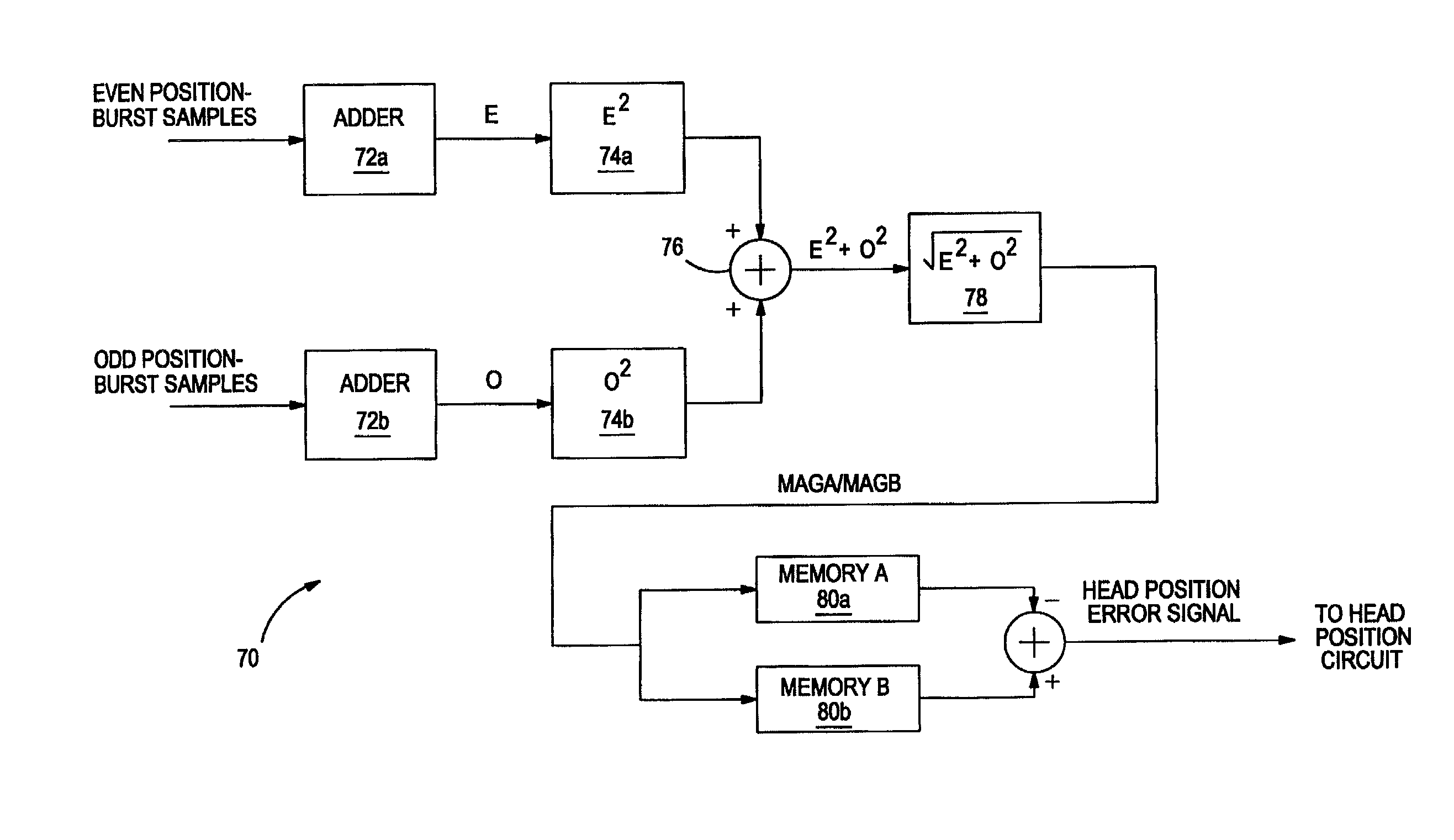
[0032]FIG. 6 is a block diagram of a position-burst demodulator 70 according to an embodiment of the invention. As discussed below in conjunction with FIG. 7, the circuit uses a variation of a known trigonometric identity to calculate the magnitude of a position burst (FIGS. 4 and 5 ) independently of the synchronization, or lack thereof, between the sample clock (FIG. 5) and the postion burst. In the embodiment discussed in conjunction with FIG. 6, the demodulator 70 is part of a servo circuit (FIG. 8) and provides a head-position-error signal to a head-position circuit (FIG. 9). Alternatively, the demodulator 70 may be part of the head-position circuit.

[0033]FIG. 7 is a phase diagram of a positive half period of the burst sinusoid of FIG. 5, and illustrates how the position-burst demodulator 70 of FIG. 6 calculates a synchronization-independent value for the magnitude Y of the burst sinusoid. Specifically, samples 90 and 92 are 90° apart. Therefore, one can calculate the amplitude...


PUM

PropertyMeasurementUnit
data-storage densitiesaaaaaaaaaa
storage densityaaaaaaaaaa
frequencyaaaaaaaaaa

Abstract

A new technique for Hard Disk Drive (HDD) servo-burst demodulation is provided. A 4-samples per dibit Discrete Fourier Transform (DFT) amplitude estimation is used to calculate the read-head servo-position error signal. Comparatively, the conventional method of burst demodulation—called burst integration—typically uses more than 8 samples / dibit. Consequently, the new 4-samples / dibit DFT burst-demodulation scheme requires fewer samples per dibit than does burst integration, thus reducing the disk space occupied by the burst data while increasing the performance as compared to burst integration. Furthermore, the DFT scheme does not require the samples to be synchronized to any particular points of the servo burst, and can include an averaging algorithm that further improves performance for a given Signal to Noise Ratio (SNR). Moreover, the same sample-clocking circuit that detects the Gray Code servo information can also implement the DFT burst-demodulation scheme to demodulate the servo burst.

Description

CROSS-REFERENCE TO RELATED APPLICATIONS[0001]This application is related to U.S. Patent Application Ser. Nos. 60 / 301,505 entitled “DATA-STORAGE DISK HAVING FEW OR NO SPIN-UP WEDGES AND METHOD FOR WRITING SERVO WEDGES ONTO THE DISK,” 60 / 301,504 entitled “CIRCUIT AND METHOD FOR DETECTING A SERVO WEDGE ON SPIN UP OF A DATA-STORAGE DISK”, 60 / 301,469 entitled “CIRCUIT AND METHOD FOR DETECTING A SPIN-UP WEDGE AND A CORRESPONDING SERVO WEDGE ON SPIN UP OF A DATA-STORAGE DISK”, 60 / 301,506 entitled “A DATA CODE AND METHOD FOR CODING DATA”, Ser. No. 09 / 993,779 entitled “CIRCUIT AND METHOD FOR DETECTING THE PHASE OF A SERVO SIGNAL”, 60 / 301,503 entitled “SERVO CIRCUIT HAVING A SYNCHRONOUS SERVO CHANNEL AND METHOD FOR SYNCHRONOUSLY RECOVERING SERVO DATA”, which were filed on the same day as the present application and which are incorporated by reference.FIELD OF THE INVENTION[0002]The invention is related generally to electronic circuits, and more particularly to a circuit and method for demodul...

Claims


Application Information

Patent Timeline
Patent Type & Authority Patents(United States)
IPC IPC(8): G11B5/02G11B5/596G11B21/10
CPCG11B5/59688G11B5/59655
Inventor HEYDARI, FEREIDOONOZDEMIR, HAKAN
Owner STMICROELECTRONICS SRL
Why Eureka
Try Eureka