Construction machine and method for manufacturing the same

a construction machine and construction method technology, applied in the field of construction machines, can solve the problems of improper height setting of the bottom plate, difficulty in attaching the device and the guard panel to the support, and difficulty in adjusting the height of the perpendicular member

Inactive Publication Date: 2008-10-07
KOBELCO CONSTR MASCH CO LTD
View PDF13 Cites 8 Cited by
  • Summary
  • Abstract
  • Description
  • Claims
  • Application Information

AI Technical Summary

Benefits of technology

[0011]Accordingly, it is an object of the present invention to provide a construction machine that enables a simple attachment process of perpendicular members, such as supporters, to a bottom plate of an upper frame while maintaining the perpendicularity and a proper height setting of each perpendicular member. Moreover, it is another object of the present invention to provide a method for manufacturing such a construction machine.
[0013]Accordingly, since each attachment hole extends substantially perpendicular to the bottom plate of the upper frame and the lower end of the perpendicular member is welded to the bottom plate while being engaged with the corresponding attachment hole, the perpendicularity of the perpendicular member can be ensured regardless of welding distortion or a fabrication error in the bottom plate, or a truncation error in the perpendicular member.
[0014]Furthermore, since the height of the perpendicular member can be adjusted within the engagement portion between the lower end of the perpendicular member and its corresponding attachment hole, an accurate height adjustment of the perpendicular member can be achieved.
[0015]Although the expression “at least one attachment hole which extends substantially perpendicular to the bottom plate” is being used above, each attachment hole does not necessarily have to be exactly perpendicular to the bottom plate. In detail, the perpendicularity of each attachment hole is permissible to an extent such that each attachment hole does not cause problems in attaching the devices to the supporters.

Problems solved by technology

However, when assembling together the main components of the rotating body, such as main frame components, there are cases where the bottom plate is bent due to welding distortion.
Consequently, this means that the supporters have to be fixed to a slanted surface and thus may deteriorate the perpendicularity of the supporters, and moreover, may lead to improper height setting of the supporters.
As a result, this may create difficulties in attaching the devices and the guard panel to the supporters.
Furthermore, other than the welding distortion, there are also cases where the deterioration of the perpendicularity and the improper height setting of the supporters are caused due to a fabrication error in the top surface of the bottom plate or a truncation error in the supporters.
Such solutions are possible, but are problematic in view of the fact that they increase the time and number of steps required for manufacture.

Method used


Image

  • Construction machine and method for manufacturing the same
  • Construction machine and method for manufacturing the same
  • Construction machine and method for manufacturing the same

Examples


first embodiment (

FIGS. 1 to 3D)

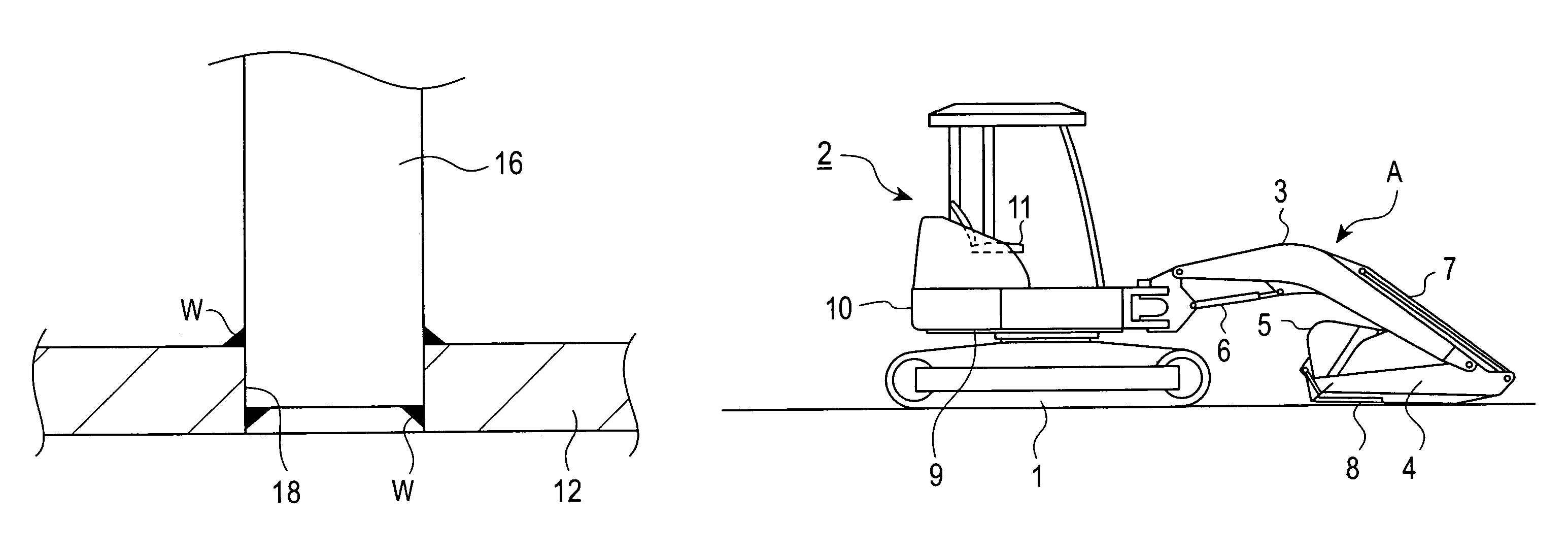
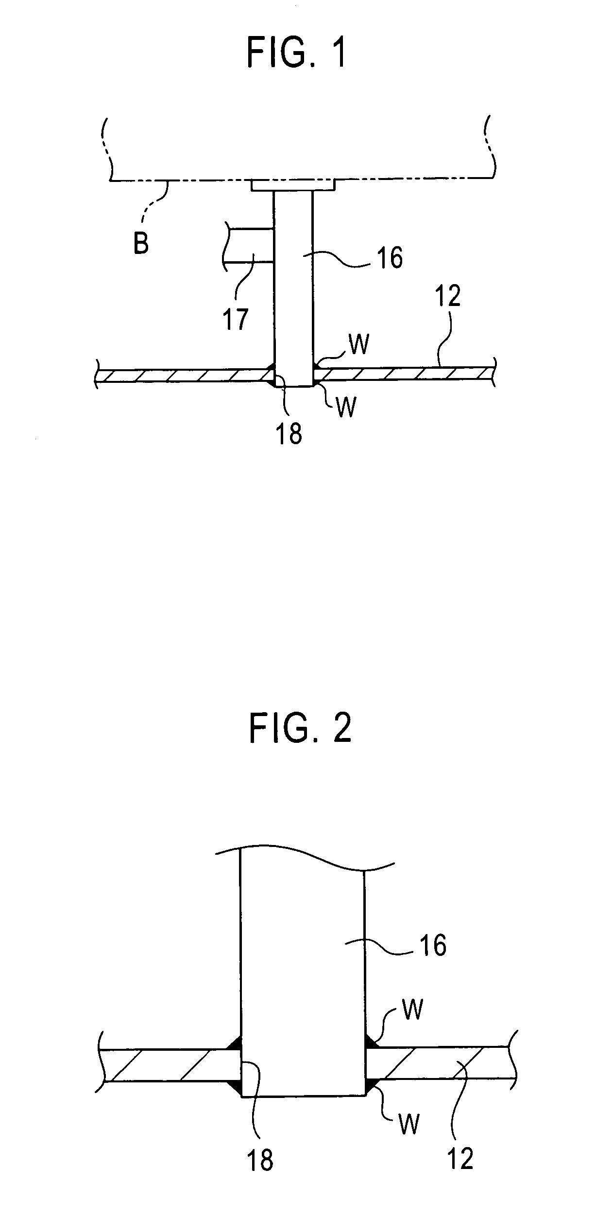
[0039]A first embodiment according to the present invention is an example in which the supporters 16 are fixed to the bottom plate 12 of the upper frame 9. As described above, the supporters 16, which are shown in FIG. 10, define the perpendicular members and are provided for holding each of the elements B.

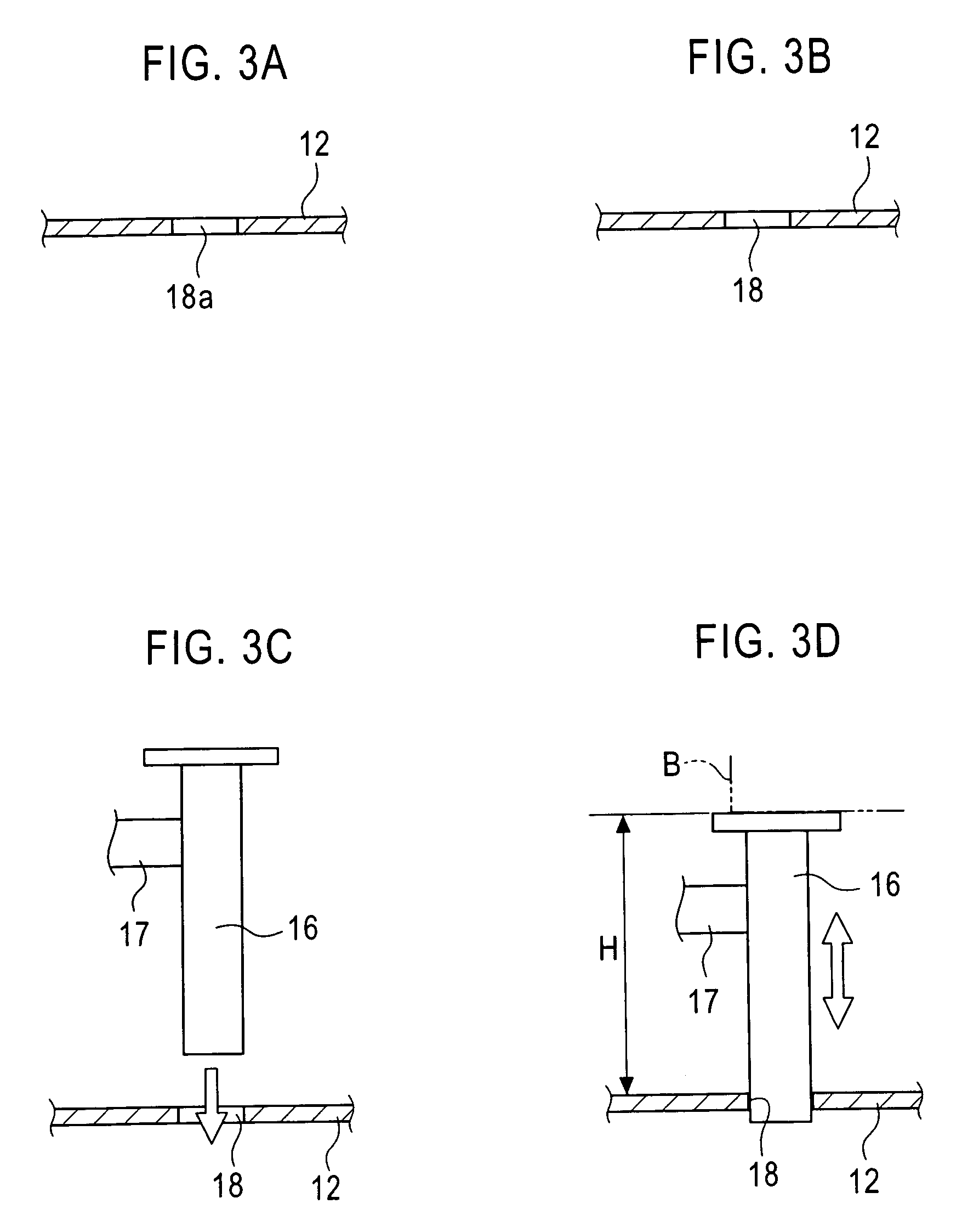
[0040]Each of the supporters 16 is a circular or rectangular pipe having a length slightly greater than the predetermined height of the upper frame 9, and has the guard-panel bracket 17 attached to the outer periphery thereof.

[0041]Each supporter 16 is engaged with one of attachment holes 18 extending through the bottom plate 12. After the height adjustment of each supporter 16 is completed, the engagement portion between the supporter 16 and the corresponding attachment hole 18 at both sides of the bottom plate 12 is welded, and one of the elements B is then disposed on the upper end of the supporter 16.

[0042]The procedure for fixing one of the supporters 16 to the ...

second and third embodiments (

FIGS. 4 and 5)

[0051]Second and third embodiments of the present invention will be described by only pointing out the differences from the first embodiment.

[0052]FIG. 4 corresponds to the second embodiment. Referring to FIG. 4, the lower end of each supporter 16 is engaged with the corresponding attachment hole 18 in an incompletely inserted state. After the height H of one of the supporters 16 is adjusted within the attachment hole 18, the supporter 16 is welded to the bottom plate 12. The reference characters W indicate the welded portions.

[0053]FIG. 5 corresponds to the third embodiment. Referring to FIG. 5, each attachment hole 18 in the third embodiment does not extend completely through the bottom plate 12. After the height H of one of the supporters 16 is adjusted within the attachment hole 18, the supporter 16 is welded to the bottom plate 12.

[0054]According to the second and third embodiments, the lower end of each supporter 16 is welded to the bottom plate 12 while the supp...

fourth embodiment (fig.6)

Fourth Embodiment (FIG. 6)

[0056]A fourth embodiment according to the present invention will now be described with reference to FIG. 6. In the fourth embodiment, the perpendicular member mentioned above is a plate member 19 having a relatively oblong structure.

[0057]In other words, the bottom edge of each of the plate members 19 is provided with insertion segments 19a (two insertion segments 19a are provided in FIG. 6) which protrude downward from the plate member 19. The insertion segments 19a are separated by a predetermined distance in the longitudinal direction of the plate member 19. On the other hand, the bottom plate 12 is provided with the attachment holes 18 at positions corresponding to the insertion segments 19a. Each of the insertion segments 19a is welded to the bottom plate 12 while being engaged with the corresponding attachment hole 18.

[0058]Consequently, in comparison with a case where an attachment slot corresponding to the overall length of each oblong plate member...


PUM

PropertyMeasurementUnit
distanceaaaaaaaaaa
heightaaaaaaaaaa
thicknessaaaaaaaaaa

Abstract

A construction machine includes a lower traveling body on which an upper rotating body is rotatably disposed. The rotating body includes an upper frame provided with a bottom plate and a supporter acting as a perpendicular member. The bottom plate has an attachment hole extending substantially perpendicular to the bottom plate. The supporter is welded substantially perpendicular to the bottom plate while one end of the supporter is engaged with the attachment hole. Accordingly, the supporter can be easily fixed to the bottom plate while maintaining the perpendicularity and a proper height setting of the supporter.

Description

BACKGROUND OF THE INVENTION[0001]1. Field of the Invention[0002]The present invention relates to construction machines, such as hydraulic excavators, and to a method for manufacturing such construction machines.[0003]2. Description of the Related Art[0004]Hydraulic excavators are generally provided with an upper rotating body which includes a frame. The frame has a bottom plate which is provided with supporters for supporting devices, such as an operating oil tank and a fuel tank.[0005]Conventionally, the supporters are attached to the bottom plate by welding the lower end of each supporter to the top surface of the bottom plate.[0006]In such a case, since the supporters are attached to devices and guard panels, the supporters must be properly adjusted for height and perpendicularity.[0007]However, when assembling together the main components of the rotating body, such as main frame components, there are cases where the bottom plate is bent due to welding distortion. Such bending of...

Claims


Application Information

Patent Timeline
Patent Type & Authority Patents(United States)
IPC IPC(8): B62D33/06B62D21/18B62D27/02E02F9/08
CPCB62D21/186B62D27/02E02F9/0816
Inventor KATAYAMA, NAOHIROOKUNISHI, TAKAYUKI
Owner KOBELCO CONSTR MASCH CO LTD
Why Eureka
Try Eureka