System and method for using hot gas reheat for humidity control

a technology of humidity control and hot gas, which is applied in the direction of domestic cooling equipment, heating types, instruments, etc., can solve the problems of affecting the comfort of cooling in the interior space of the building, and affecting the efficiency of cooling system operation, so as to achieve the effect of improving efficiency and ensuring the comfort of cooling

Active Publication Date: 2008-10-14
JOHNSON CONTROLS TYCO IP HLDG LLP
View PDF42 Cites 32 Cited by
  • Summary
  • Abstract
  • Description
  • Claims
  • Application Information

AI Technical Summary

Benefits of technology

[0011]An advantage of the present invention is that refrigerant is not trapped in an inactive coil when switching between cooling cycles and reheat (dehumidification) cycles, thereby assuring that adequate refrigerant is available to the compressor.
[0012]Another advantage of the present invention is that comfort cooling in the interior space of a building is not compromised when there is a demand for humidity control.
[0013]Yet another advantage is that refrigerant can be quickly removed from a condenser, regardless of ambient conditions, to a location within the system where the refrigerant is available on demand to the compressor when the system is not in a cooling mode.
[0014]Still another advantage of the arrangement of the present invention is that the reheat by-pass circuit utilizes heat that otherwise would be transferred to the outdoor condenser, which is an energy savings, and the removal of trapped refrigerant from the inactive condenser or the inactive reheat coil allows the system to operate more efficiently.

Problems solved by technology

As the outdoor temperature falls, the amount of refrigerant that becomes trapped in the condenser coil will increase, resulting in a drop in the quantity of refrigeration available in the remainder of the refrigerant system to accomplish dehumidification.
Without adequate refrigerant in the dehumidification circuit, operational problems will occur with the air delivery system.
The refrigerant can become trapped in the condenser coil, and if switching is required to the cooling mode, additional refrigerant can be trapped in the reheat circuit.
One of the problems is decreased system capacity as the refrigerant normally available in a properly operating system is trapped in the condenser coil and not available to the compressor.
Associated with this problem is inadequate suction pressure at the compressor, since the gas refrigerant that normally is available to the compressor from the evaporator is trapped as a liquid in the condenser.

Method used


Image

  • System and method for using hot gas reheat for humidity control
  • System and method for using hot gas reheat for humidity control
  • System and method for using hot gas reheat for humidity control

Examples


Embodiment Construction

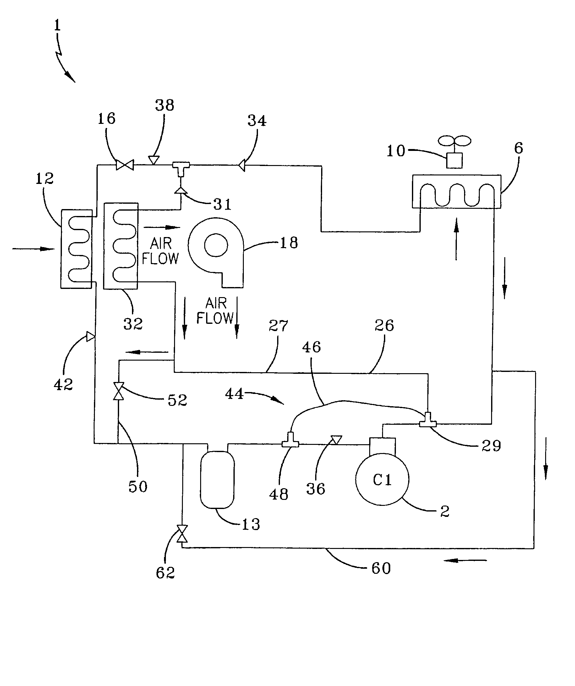
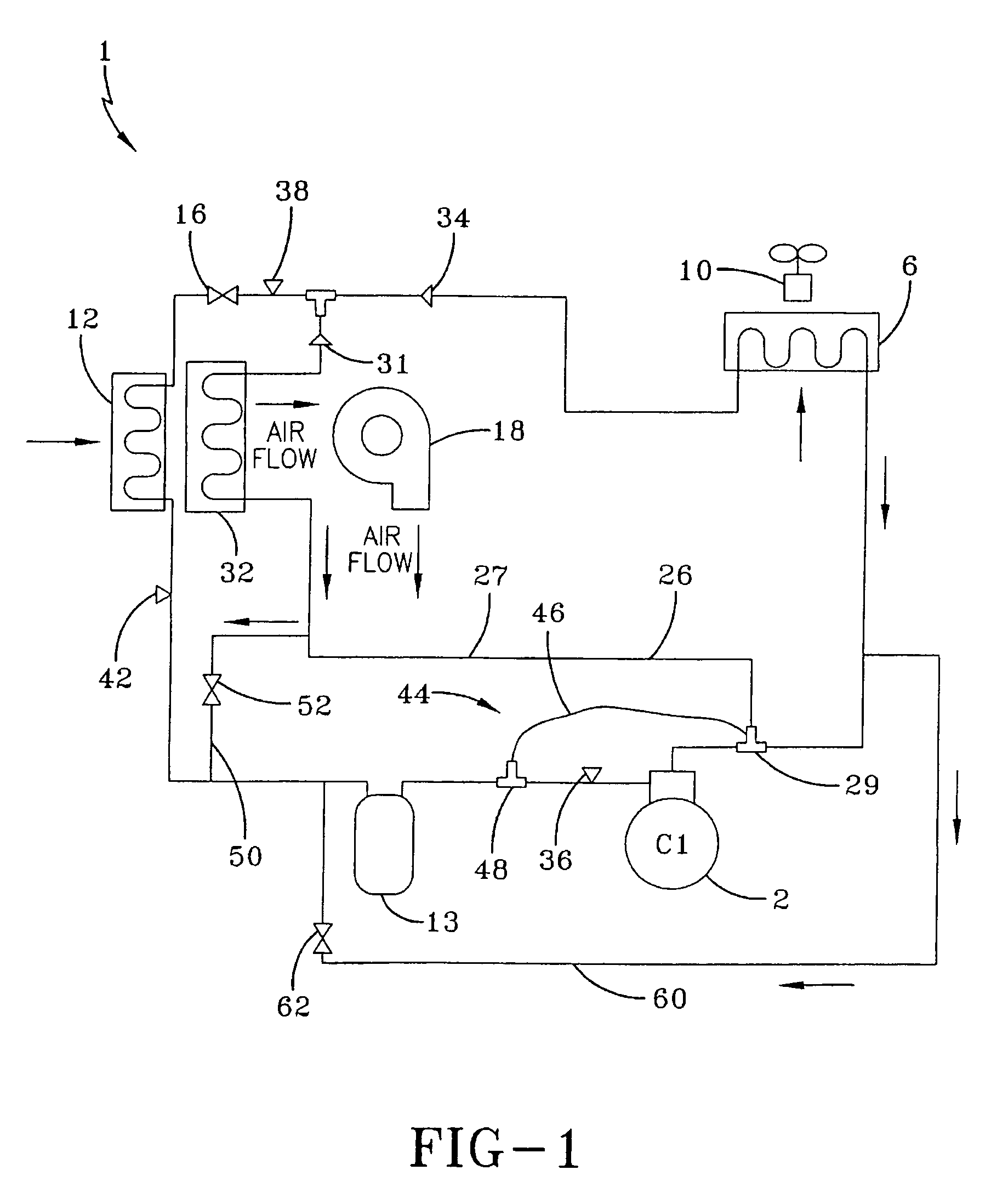
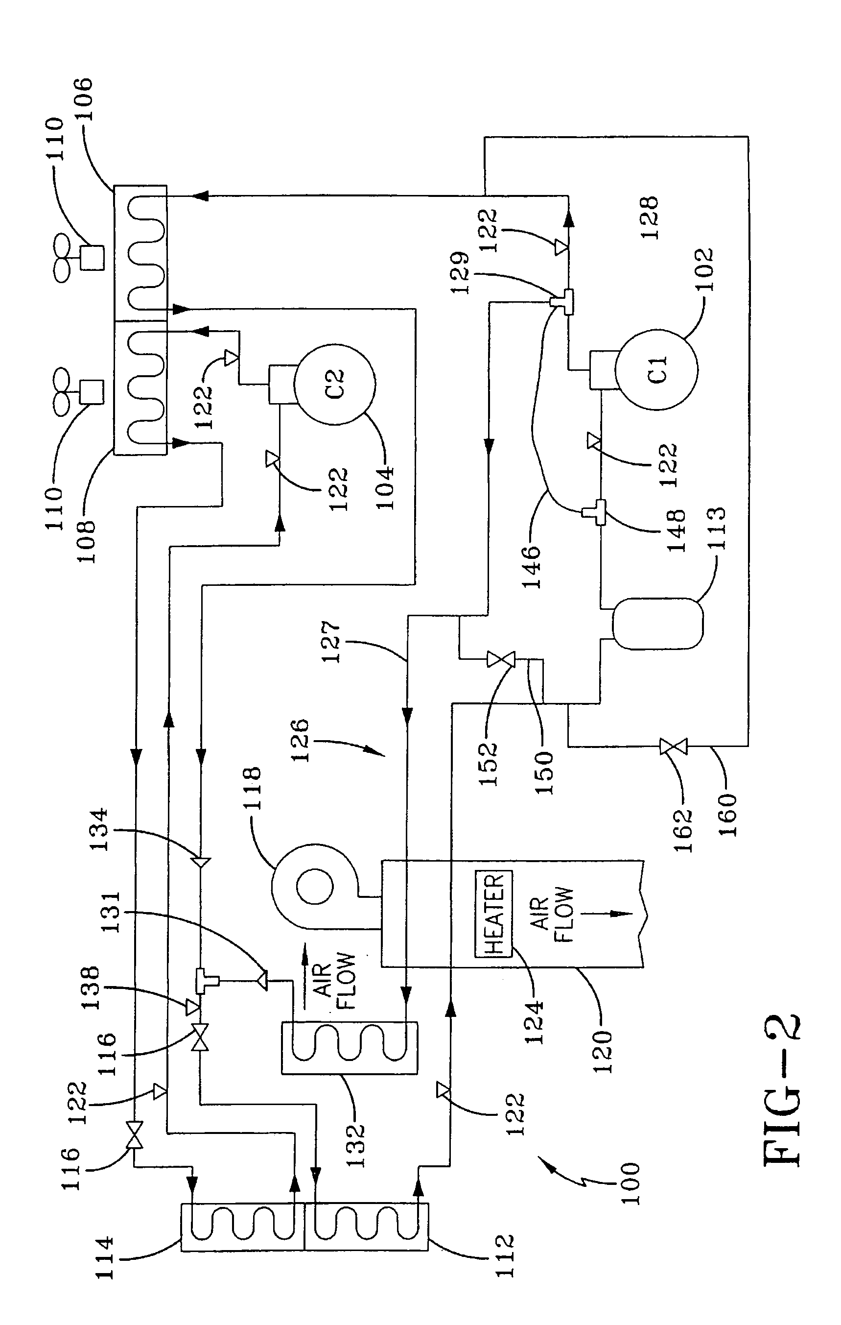
[0020]FIG. 1 illustrates one embodiment of a ventilation and air conditioning (HVAC) system 1 for an interior space of a building. The HVAC system 1 provides both air conditioning control and humidity control to an interior space of a building. The HVAC system 1 typically is a single stage cooling system using compressor 2 to provide cooling capacity and humidity control in an interior space of a building which requires cooling and / or humidity control. Compressor 2 may be a any type of a compressor, such as screw compressor, a scroll compressor, a centrifugal compressor, a rotary compressor or a reciprocating compressor. In most moderate climates where cooling and humidity control is required, such as in the refrigeration section of a commercial establishment, for example a supermarket, heating is not required throughout the year. In those climates where extreme cold temperatures exist, such as for example, in the northern portions of the continental United States, Alaska and Canada...


PUM


Abstract

A humidity control method is provided for a multi-stage cooling system having two or more refrigerant circuits that balances humidity control and cooling demand. Each refrigerant circuit includes a compressor, a condenser and an evaporator. A hot gas reheat circuit having a hot gas reheat coil is connected to one of the refrigerant circuits and is placed in fluid communication with the output airflow from the evaporator of that refrigerant circuit to provide additional dehumidification to the air when humidity control is requested. The hot gas reheat circuit bypasses the condenser of the refrigerant circuit during humidity control. Humidity control is only performed during cooling operations and ventilation operations.

Description

CROSS REFERENCE TO RELATED APPLICATIONS[0001]This application is a continuation of application Ser. No. 10 / 694,316 filed Oct. 27, 2003, which is herein incorporated by reference in its entirety, which claims priority to U.S. Provisional Application No. 60 / 425,172, filed Nov. 8, 2002.FIELD OF THE INVENTION[0002]The present invention relates generally to a humidity control application for a cooling system. More specifically, the present invention relates to a method for performing humidity control using hot gas reheat in a two-stage cooling unit.BACKGROUND OF THE INVENTION[0003]Air delivery systems, such as used in commercial applications, typically are systems that can be used to cool or to accomplish dehumidification when ambient conditions are such that there is no demand for cooling. This demand for dehumidification can often occur on days when the temperature is cool and there is a high humidity level, such as damp, rainy spring and fall days. Under such conditions, it may be nec...

Claims


Application Information

Patent Timeline
Patent Type & Authority Patents(United States)
IPC IPC(8): F25B29/00F25B13/00F25B41/00F25B49/00F25D17/04F24F3/153F25B41/04
CPCF24F3/153F25B41/04F25B2400/04F25B2400/061F25B2400/19F25B6/02F25B49/02F25B2400/06F25B41/20
Inventor KNIGHT, JOHN TERRYBELLAH, STEPHEN WAYNEPICKLE, STEPHEN BLAKE
Owner JOHNSON CONTROLS TYCO IP HLDG LLP
Why Eureka
Try Eureka