Engine

a technology for engines and oil, applied in the field of engines, can solve problems such as pressure loss of oil, and achieve the effect of reducing the pressure loss of oil

Active Publication Date: 2008-10-14
KAWASAKI MOTORS LTD
View PDF14 Cites 5 Cited by
  • Summary
  • Abstract
  • Description
  • Claims
  • Application Information

AI Technical Summary

Benefits of technology

[0006]The present invention addresses the above described conditions, and an object of the present invention is to provide an engine equipped with a hydraulically-powered device that is capable of reducing a pressure loss of oil delivered from an oil pump for lubrication and for driving a hydraulically-powered device to the hydraulically-powered device.
[0008]The oil cooler serves to water-cool or air-cool an outer wall of a sinuous oil passage thereof in which the oil flows to lower the temperature of the oil. Because of the resistance to the oil flowing in the sinuous oil passage, the oil generates a pressure loss. The oil cooler is typically disposed in close proximity to an outlet of the oil pump to cool the oil before the oil lubricates engine components. In the above construction, since the branched oil passage for the hydraulically-powered device through which the oil is delivered to the hydraulically-powered device branches in a location of the oil passage extending between the oil pump and the oil cooler, and the oil that is output from the oil pump and that flows through the branched oil passage for the hydraulically-powered device does not pass the oil cooler, the pressure loss generated in the oil delivered to the hydraulically-powered device can be reduced. Thus, a sufficient oil pressure can be obtained even during low engine speed. This enables the use of an oil pump with a small volume in the engine. As a result, the size and cost of the engine can be reduced. Furthermore, since an input torque of the oil pump can be reduced, an output efficiency of the engine can be improved.
[0012]In such a construction, since the long oil passage for the hydraulically-powered device that extends from the lower portion of the engine to the upper portion of the engine is not mounted in the interior of the engine, the size of the engine can be reduced.
[0014]In such a construction, since the oil guiding pipe is externally attached to the engine easily, it is easily applicable to the existing engine. As a result, the oil guiding pipe can be employed in a variety of engines. In addition, since the oil guiding pipe is easily removed, maintenance of the oil guiding pipe is improved.
[0016]Since the elastic pipe forms a part of the oil guiding pipe, the entire oil guiding pipe is able to absorb a load applied on the metal pipe to reduce a stress exerted on the metal pipe. In addition, since the oil guiding pipe includes separate pipes as described above, it is easily assembled into the engine. Further, since the elastic pipe forming a part of the oil guiding pipe allows for dimension errors when the oil guiding pipe is mounted to the engine, desired dimension precision can be reduced, and hence a manufacturing cost of the engine can be reduced.

Problems solved by technology

Because of the resistance to the oil flowing in the sinuous oil passage, the oil generates a pressure loss.

Method used


Image

  • Engine
  • Engine
  • Engine

Examples


embodiment 1

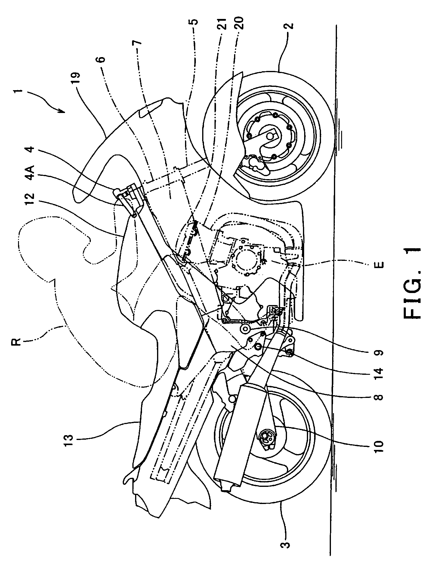
[0038]FIG. 1 is a right side view of a motorcycle 1 in which an engine E according to an embodiment of the present invention is mounted. The motorcycle 1 is a road sport type motorcycle in which a rider R rides with an upper body leaning forward. Herein, directions are generally referenced from the perspective of the rider R mounting the motorcycle 1 of FIG. 1.

[0039]Turning now to FIG. 1, the motorcycle 1 includes a front wheel 2 and a rear wheel 3. The front wheel 2 is rotatably mounted to a lower region of a front fork 5 extending substantially vertically. The front fork 5 is mounted on a steering shaft (not shown) by an upper bracket (not shown) attached to an upper end thereof, and an under bracket located below the upper bracket. The steering shaft is rotatably supported by a head pipe 6. A bar-type steering handle 4 extending in a rightward and leftward direction is attached to the upper bracket. When the rider R rotates the steering handle 4 clockwise or counterclockwise, the...

embodiment 2

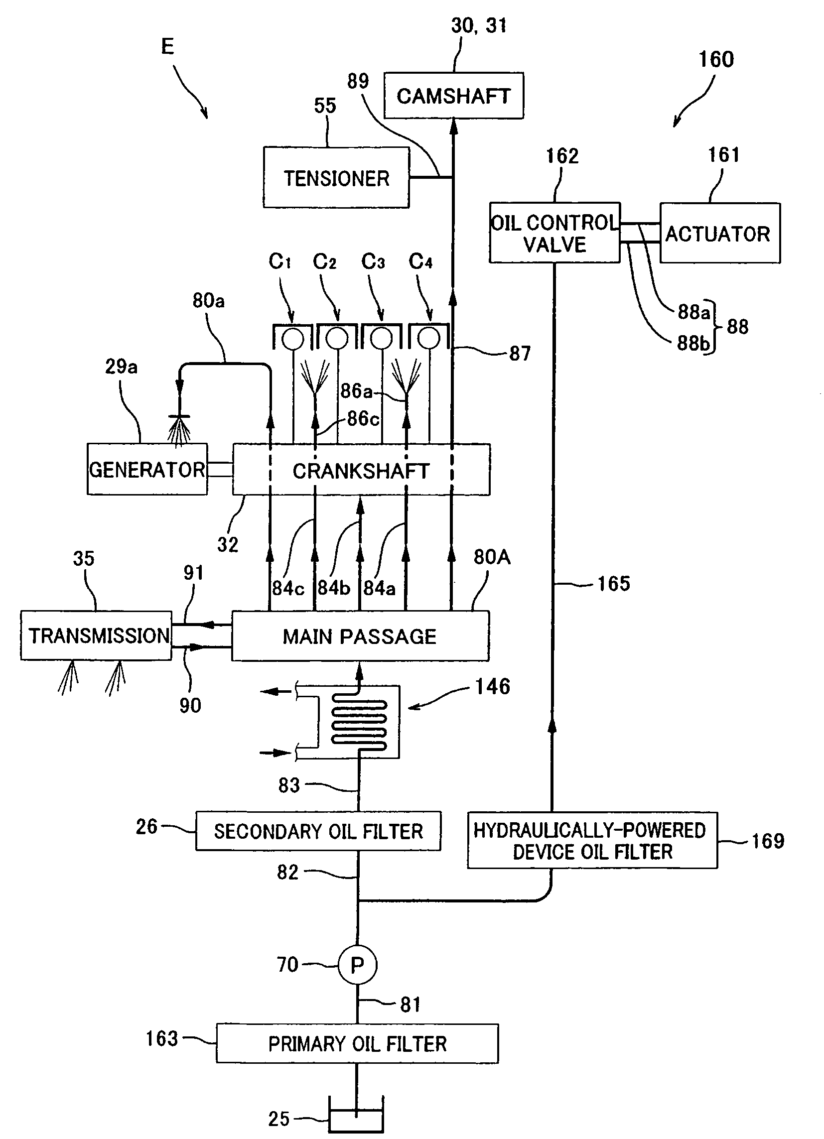
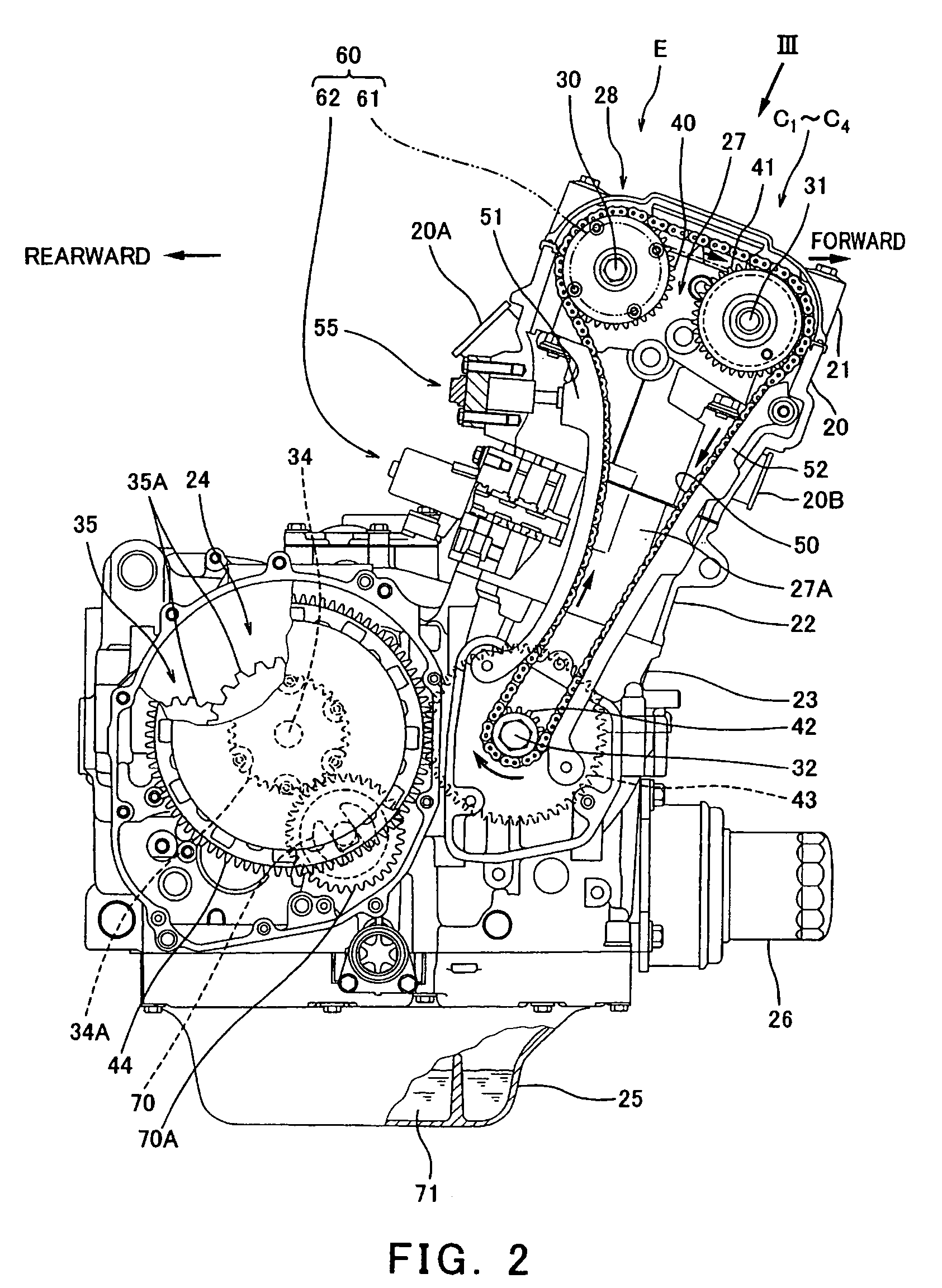
[0085]Subsequently, a second embodiment of the present invention will be described. FIG. 10 is a right side view of the engine E according to the second embodiment. FIG. 11 is a perspective view of the engine E, from which the cylinder head 20 is removed. FIG. 12 is a plan view of the engine E of FIG. 11. FIG. 13 is a cross-sectional view of the engine E, taken substantially along line XIII-XIII of FIG. 12. FIG. 14 is a view schematically showing a construction of oil passages of the engine E.

[0086]Turning now to FIGS. 13 and 14, a primary oil filter 163 is attached to a first oil passage 81 extending between the oil pan 25 that reserves the oil at the lower portion of the engine E and the oil pump 70. A second oil passage 82 is coupled to an output side of the oil pump 70 and to a secondary oil filter 26. In FIG. 13, a passage downstream of a bent portion 82a of the second oil passage 82, which is connected to the secondary oil filter 26, is not shown. A third oil passage 83 is cou...

embodiment 3

[0092]Subsequently, a third embodiment of the present invention will be described. FIG. 15 is a view schematically showing a construction of the oil passages of the engine E according to the third embodiment. As shown in FIG. 15, in this embodiment, the oil passage 165 for the hydraulically-powered device that branches in a location of the third oil passage 83 extending between the oil cooler 146 and the secondary oil filter 26 further branches to feed the oil to the hydraulically-powered tensioner 55.

[0093]In the above construction, since the oil pressure without the pressure loss that may be caused by the oil cooler 146 is fed to the hydraulically-powered tensioner 55, the tensioner 55 is able to efficiently apply a forward force to the chain guide 51 (see FIG. 2), thereby applying a suitable tension to the timing chain 50. The other construction is identical to that of the first embodiment, and will not be further described.


PUM


Abstract

An engine including an oil passage through which oil output from an oil pump flows, an oil cooler mounted to the oil passage, and a branched oil passage for a hydraulically-powered device of the engine that is configured to branch in a location of the oil passage extending from the oil pump to the oil cooler to deliver the oil to the hydraulically-powered device.

Description

TECHNICAL FIELD[0001]The present invention generally relates to an engine. More particularly, the present invention relates to an oil feeding system that delivers oil output from an oil pump to the engine to lubricate engine components and includes a branched oil passage to deliver the oil to a hydraulically-powered device.BACKGROUND ART[0002]In engines mounted in leisure vehicles such as motorcycles, oil reserved in an oil pan provided at a bottom portion of the engine or in an oil tank externally and separately mounted thereon is suctioned up by an oil pump driven in synchronization with an engine speed of the engine and is delivered through oil passages provided within the engine to lubricate and cool a crankshaft, a camshaft, or a transmission. In recent years, some engines have been equipped with a hydraulically-powered variable valve timing system configured to change a phase angle of the camshaft with respect to the crankshaft or a hydraulically-powered tensioner of a camshaf...

Claims


Application Information

Patent Timeline
Patent Type & Authority Patents(United States)
IPC IPC(8): F01M1/02F01L1/34
CPCF01L1/02F01L1/022F01L1/053F01L1/34F01L1/3442F01M5/002F01M11/02F01L2001/34423F01L2810/02
Inventor SUZUKI, KOZOARIMA, HISATOYOTSUBONE, TOSHIYUKI
Owner KAWASAKI MOTORS LTD
Why Eureka
Try Eureka