Device, including a quick-tightening mechanism, for a cantilevered mounting of a wheel to the frame of a bicycle

a technology of quick tightening mechanism and bicycle, which is applied in the direction of axle suspension, axle unit, cycle equipment, etc., can solve the problems of not being particularly practical, not only taking longer to achieve the connection of the nut, but also increasing the axial space requirement of the mechanism

Inactive Publication Date: 2008-10-14
MAVIC SA
View PDF33 Cites 19 Cited by
  • Summary
  • Abstract
  • Description
  • Claims
  • Application Information

AI Technical Summary

Benefits of technology

[0011]An object of the invention is to overcome the aforementioned drawbacks, and in particular to provide a device for mounting a wheel to a single cantilevered arm of a frame of a bicycle, and for demounting the wheel therefrom, hereafter referred to as a mounting device, which can be used with a quick tightening mechanism, and which is compact in the axial direction.
[0012]Another object of invention is to provide a wheel mounting device in which the tightening mechanism has improved efficiency.
[0013]Another object of the invention is to provide a wheel mounting device, the tightening mechanism of which substantially reduces the axial space requirement.

Problems solved by technology

Connecting with a nut not only takes longer to accomplish, it is also not particularly practical as it requires a tool to be used in order to obtain adequate tightening and release.
This considerably increases the axial space requirement of the mechanism.
However, it is known that the axial space requirement in a device for mounting a wheel is critical, particularly for the rear wheel, where the mounting of the wheel itself must share the axial volume with the rolling bearings, the driving gears and, possibly, the brake disk.
Moreover, the efficiency of such a device is very minimal due to substantial friction between the various parts of the mechanism, especially between the clamps and inner surface of the cone.
The lever is mounted on an axle and includes a cam, the friction of which causes a loss in the tightening mechanism efficiency.
This lever accompanies the wheel in its rotational movement and thereby constitutes a danger.
Indeed, elements not related to the bicycle, such as cables or wires, may become entangled around the lever.

Method used


Image

  • Device, including a quick-tightening mechanism, for a cantilevered mounting of a wheel to the frame of a bicycle
  • Device, including a quick-tightening mechanism, for a cantilevered mounting of a wheel to the frame of a bicycle
  • Device, including a quick-tightening mechanism, for a cantilevered mounting of a wheel to the frame of a bicycle

Examples


first embodiment

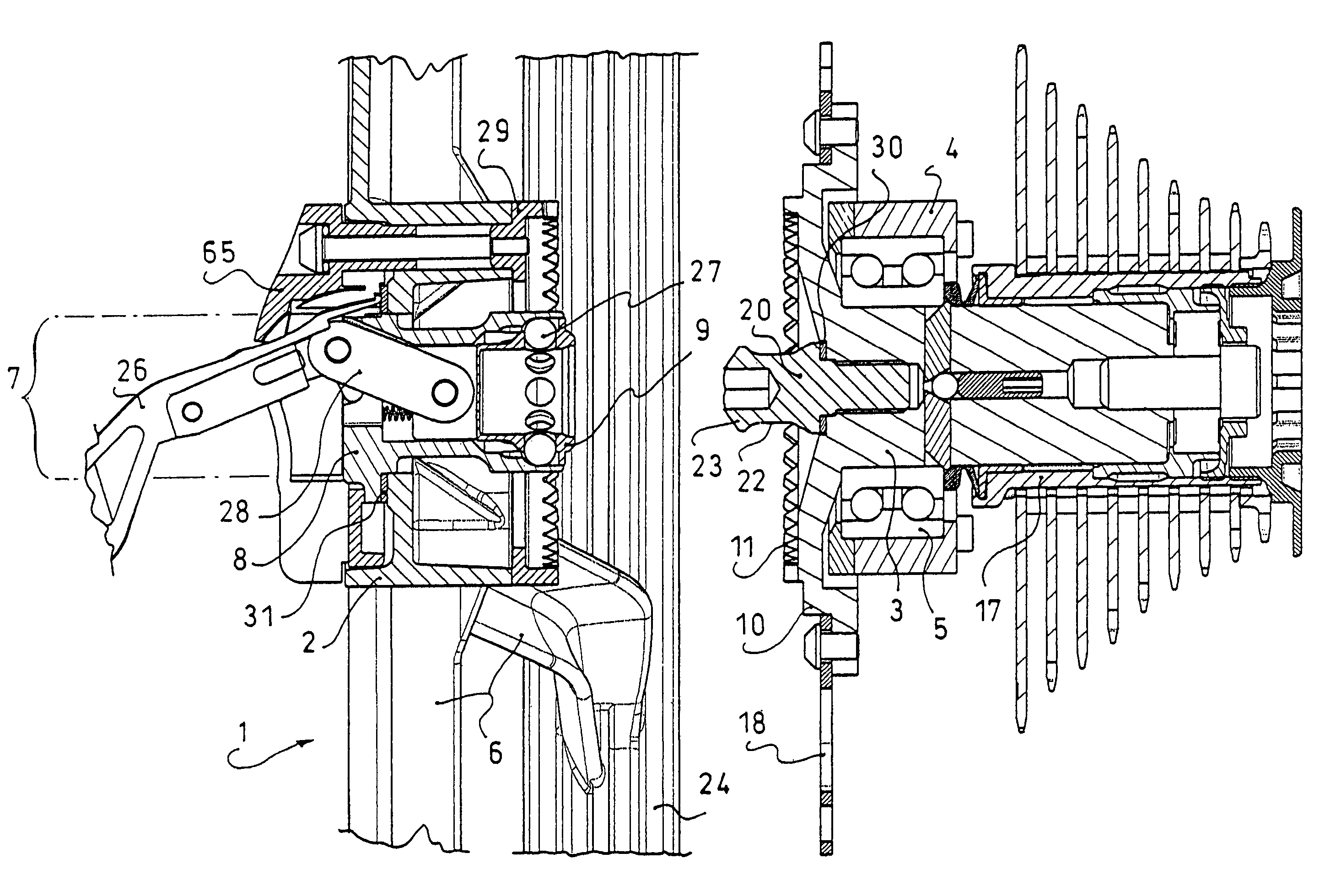
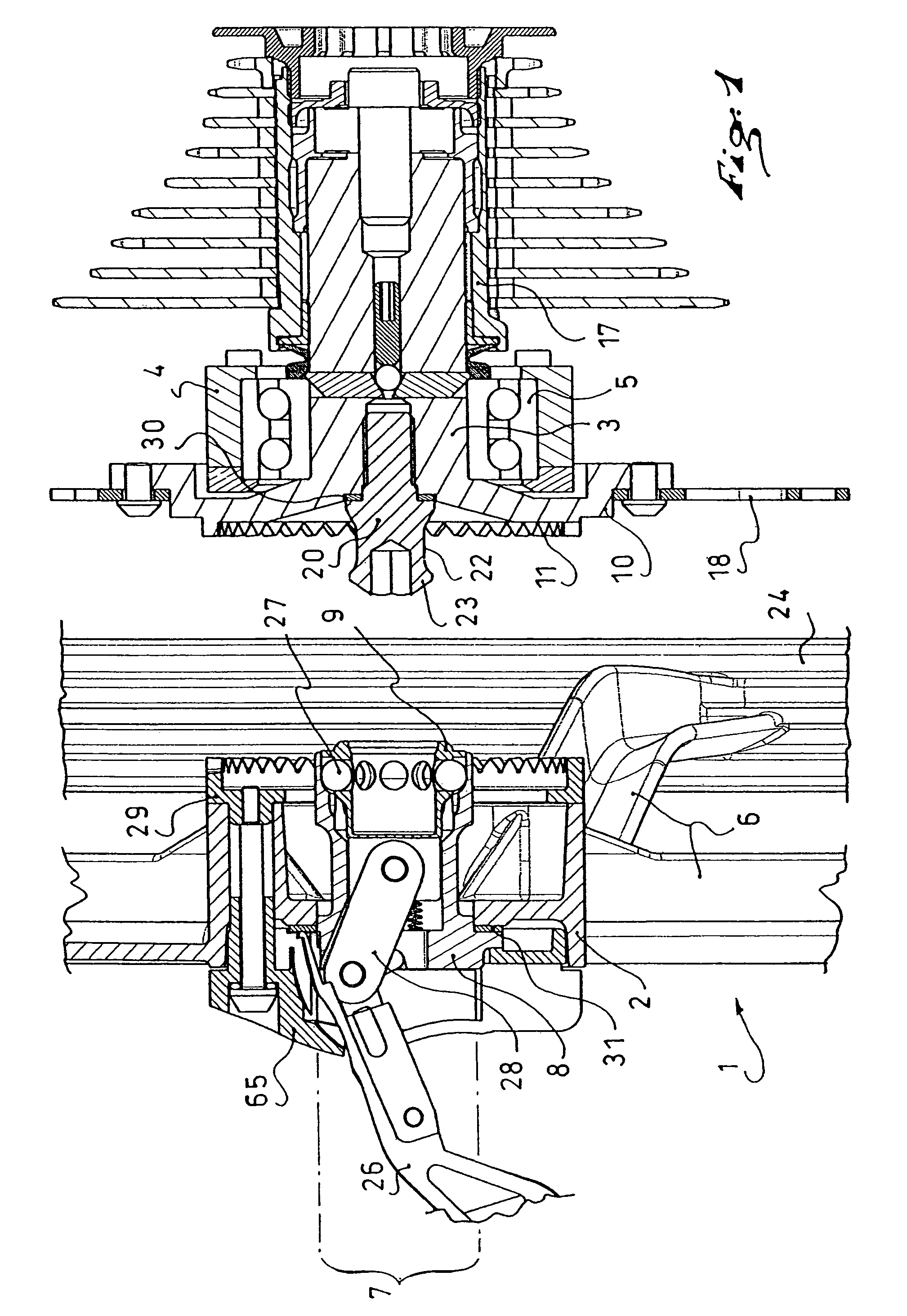
[0050]FIG. 1 illustrates the wheel mounting device according to the invention. The right portion of FIG. 1 represents the bicycle, while the left portion represents the wheel. The bicycle is only visible from the end of the frame 4 on which the inner hub 3 is fixed. Although further details of the bicycle itself, including the bicycle frame, are not necessary to understand the invention, the invention can be embodied with a bicycle like that disclosed, for example, in the commonly owned U.S. Patent Application No. U.S. Patent Application Publication No. 2006 / 0108858, the disclosure of which is hereby incorporated by reference thereto in its entirety, and family member PCT International Publication No. WO 2004 / 108515. Those disclosures are not to be considered limiting to the invention, as the invention can be implemented with other bicycle details.

[0051]The inner hub 3 of the bicycle, shown on the right portion of FIG. 1, is rotatably mounted by means of rolling bearings 5, or other...

second embodiment

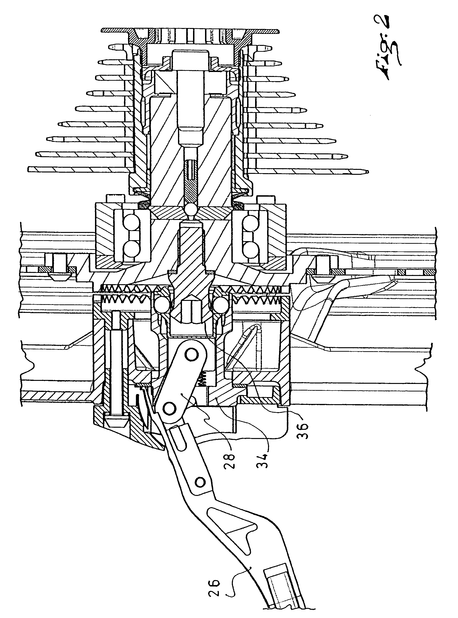
[0065]FIG. 6 illustrates the invention. The rear wheel 1 includes a rim and an outer hub 2 connected to one another by a plurality of compression spokes. As in the preceding embodiment, the compression spokes are not rectilinear, but have an offset so as to bring the median plane of the wheel, defined by the center of the rim, as close to the median plane of the frame 4 as possible. The outer hub 2 includes a crown 29 having a diameter greater than 50 mm, and at the top of which a plurality of teeth 11 are arranged. A pin 20, provided at its end with a groove 22 and a chamfered end piece 23, is arranged at the center of the crown. The inner hub 3 is rotatably mounted in a bore of the frame 4 by means of a ball bearing 5. The hub includes a cylindrical body 16 on which the free-wheel body is mounted, and a plate 10 used for attaching a braking disk and for arranging an axial support in the form of a plurality of teeth.

[0066]The female elements of the tightening mechanism are arranged...

third embodiment

[0067]FIG. 7 shows the invention. The outer hub 2 of the wheel includes an axial support arrangement in the form of a plurality of teeth distributed on a crown. A shouldered cavity 43 is arranged within this crown.

[0068]The inner hub 3 includes a plate at the periphery of which is arranged an axial support arrangement constituted by teeth complementary to those arranged on the outer hub. A bushing 40 that is fixed on the inner hub 3, or is made in one-piece therewith, projects from the center of the plate. The inside of this bushing is occupied by an arrangement of axial abutments and the device for positioning them. As in the preceding embodiment, the actuation of the tightening mechanism occurs by means of a rod 28 that extends within the inner hub 3 and is translationally driven by a pivotable lever. This portion of the mechanism is not shown in FIG. 7. The end of the rod 28, which is integrated into the bushing, includes an axial groove. Two pivotable cams 41 are mounted in the ...


PUM


Abstract

A device for mounting a wheel of a bicycle on a frame, including: an inner hub rotatably mounted in a portion of the frame, an outer hub forming a central zone of the wheel, a quick-tightening mechanism that includes a male portion projecting from a first of the inner and outer hubs, a female portion provided in a second of the hubs, axial abutments for retaining the outer hub supported against the inner hub, and a mechanism for positioning the axial abutments, the positioning mechanism not being active upon completion of the tightening of the wheel. The quick-tightening mechanism is equipped with a lever that is pivoted by the operator to provide the necessary force for the axial tightening of the outer hub of the wheel against the inner hub. In a particular embodiment of the invention, the axial abutments include a plurality of balls, and the mechanism for positioning the axial abutments include ramps on which the balls roll.

Description

CROSS-REFERENCE TO RELATED APPLICATIONS[0001]This application is a continuation of PCT International Patent Application No. PCT / FR2004 / 001308, filed on May 27, 2004, the disclosure of which is hereby incorporated by reference thereto in its entirety, and the priority of which is claimed under 35 U.S.C. §120, pursuant to the provisions of 35 U.S.C. §363.[0002]This application claims priority under 35 U.S.C. §119 of French Patent Application No. 03.06545, filed on May 28, 2003, the disclosure of which is hereby incorporated by reference thereto in its entirety.BACKGROUND OF THE INVENTION[0003]1. Field of the Invention[0004]The invention relates to a device for mounting a bicycle wheel to a frame with a quick-tightening mechanism, and a bicycle that includes such device. More particularly, the invention relates to such a device for mounting and demounting a bicycle wheel with a quick-tightening mechanism and, more particularly, for bicycles having frames with a projecting single arm, r...

Claims


Application Information

Patent Timeline
Patent Type & Authority Patents(United States)
IPC IPC(8): B62K25/04B62K25/00B62K25/02
CPCB62K25/005B62K25/02B62K2206/00B60B27/026
Inventor MERCAT, JEAN-PIERREHILLAIRET, JEAN-MARC
Owner MAVIC SA
Why Eureka
Try Eureka