

Flexible and extendable drill bit assembly
a drill bit and assembly technology, applied in the field of flexible drill bits, can solve the problems of additional expense, needing to replace the entire drill bit,
- Summary
- Abstract
- Description
- Claims
- Application Information
AI Technical Summary
Benefits of technology
Problems solved by technology
Method used
Image

Examples
Embodiment Construction
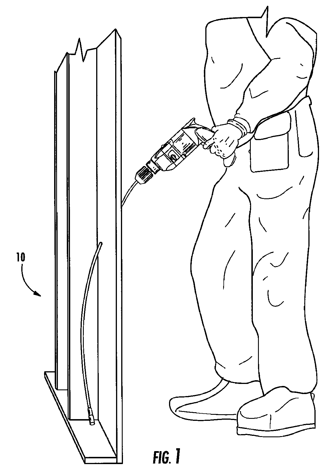
[0040]Referring now specifically to the drawings, a flexible, extendable drill bit assembly according to an embodiment of the invention is illustrated in FIG. 1 and shown generally at reference numeral 10. As shown, the drill bit assembly 10 allows a user to drill a hole through a wall to allow the user to run wiring and cabling.
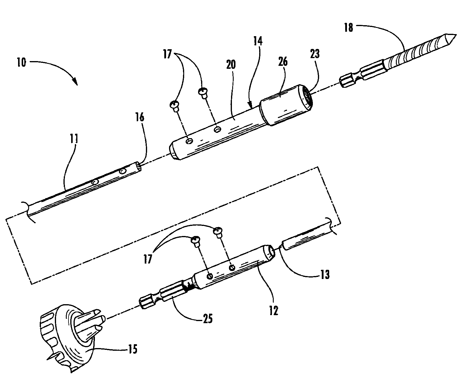
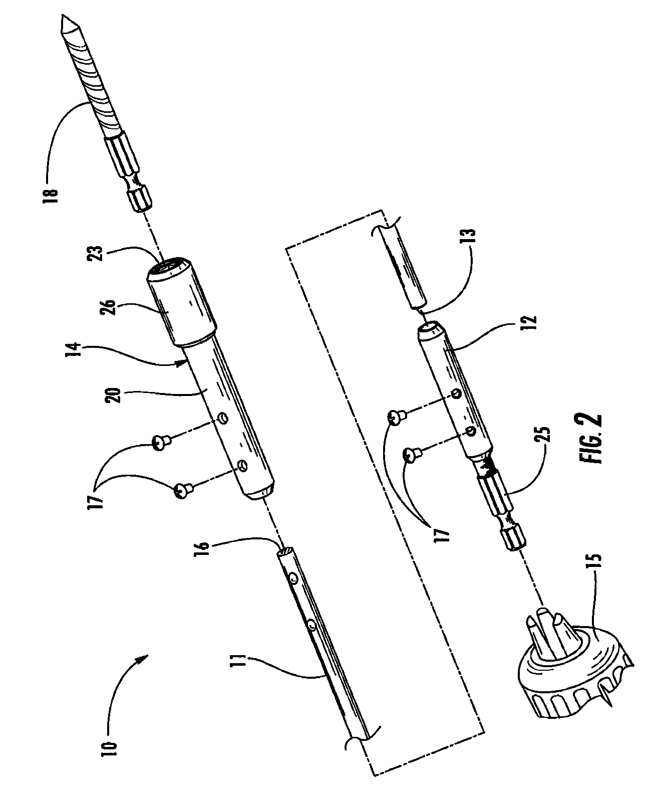
[0041]As shown in FIG. 2, the drill bit assembly 10 includes a flexible extension rod 11, a tailpiece 12 secured to a first end 13 of the rod 11 and adapted to be received by a drill 15, and a quick-release head 14 secured to an opposing second end 16 of the rod 11. The tailpiece 12 includes a shank 25 with a hexagonal profile to prevent slipping within the drill 15. As illustrated, the first and second ends 13 and 16 are received by the tailpiece 12 and head 14, respectively, and secured by set screws 17. It should be appreciated that the rod 11 may be secured to the tailpiece 12 and head 14 by any suitable fastening means, such as adhesives or welding. Fur...
PUM
| Property | Measurement | Unit |
|---|---|---|
| diameter | aaaaa | aaaaa |
| length | aaaaa | aaaaa |
| flexible | aaaaa | aaaaa |
Abstract
Description
Claims
Application Information