Optical fiber skin layer glass for optical fiber image transmission element and mechanical pipe-drawing forming method of optical fiber skin layer glass

An optical fiber cortex and optical fiber image transmission technology, which is applied in glass forming, glass forming, cladding optical fibers, etc., can solve the problem of the outer diameter dimensional accuracy and wall thickness dimensional accuracy of the cortical glass tube. It can improve the anti-devitrification performance and high temperature viscosity characteristics, increase the lower limit of crystallization temperature, and have excellent anti-devitrification performance.

Active Publication Date: 2019-08-30
CHINA BUILDING MATERIALS ACAD
View PDF10 Cites 5 Cited by
  • Summary
  • Abstract
  • Description
  • Claims
  • Application Information

AI Technical Summary

Problems solved by technology

[0004] After decades of continuous development and improvement, the method of mechanically drawing glass tubes has been widely used, but the existing Vilo method technology is not suitable for drawing large-sized glass tubes, and the diameter of the drawn tubes is about 1 to 60mm, so in the application of some multi-variety and small-batch optical fiber skinned glass tubes for optical fiber image transmission components, due to the quantity used and the viscosity characteristics of the skinned glass frit, the glass tubes are prepared by manual picking, blowing, and tube forming. Methods
Because the method of mechanical tube drawing needs to rely on large-scale tank kilns for continuous feeding, it is inconvenient to change the composition and specifications of the product, and for those glass tubes with many varieties and small batches of different components and specifications, It is extremely uneconomical to use mechanical pulling tubes
Moreover, due to the particularity of the performance of the skin glass of the optical fiber image transmission component and the limitation of the number of uses, generally only the glass tubes prepared by manual blowing and manual drawing are used, and the glass tubes prepared by manual forming are due to manual drawing. For various reasons such as uneven force, the cortical glass tube's outer diameter, wall thickness, and inner diameter roundness are far inferior to those of glass tubes pulled out by mechanical means. Especially during production
[0005] With the rapid development of low-light night vision in recent years, the production scale of optical fiber image transmission components has continued to expand, the number of applications and performance requirements have gradually increased, and the number, performance and quality of leather glass tubes required have also gradually increased. With the strengthening of the production process of optical fiber image transmission components, strict requirements on product quality and fierce competition among companies, the traditional manual drawing method is far from meeting the modern production requirements of optical fiber image transmission components.

Method used


Image

  • Optical fiber skin layer glass for optical fiber image transmission element and mechanical pipe-drawing forming method of optical fiber skin layer glass
  • Optical fiber skin layer glass for optical fiber image transmission element and mechanical pipe-drawing forming method of optical fiber skin layer glass
  • Optical fiber skin layer glass for optical fiber image transmission element and mechanical pipe-drawing forming method of optical fiber skin layer glass

Examples


Embodiment 1

[0067] (1) Melting of glass: select raw material by table 1 embodiment 1 glass composition, to the oxide compound of variable price element in the glass raw material such as Fe 2 o 3 etc. are strictly controlled, and the finished glass Fe 2 o 3 If the content is less than 1PPm, weigh quartz sand, aluminum hydroxide, boric acid or boric anhydride, sodium carbonate, potassium carbonate, calcium carbonate, strontium carbonate, zinc oxide, zirconia, titanium dioxide and antimony trioxide according to the ingredients requirements and mix them evenly , and then melted in the glass melting pool of the electric melting furnace;

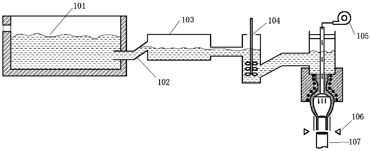
[0068](2) Clarification and homogenization: each raw material component is melted at a temperature of 1500° C. for 8 hours. After the raw material is melted into the molten glass, the molten glass flows from the discharge port of the glass melting pool 101 through the upward-inclining feed channel 102 into the clarification tank 103, and control the temper...

Embodiment 2

[0073] The actual composition of the glass refers to Example 2 in Table 1, using the same raw materials and raw material requirements as in Example 1, and adopts melting at 1450°C for 10 hours, clarification and homogenization at 1400°C for 2 hours, and annealing at 580°C. , clarification and annealing process, adopt the test condition identical with embodiment 1, have shown the basic performance of embodiment 2 sample in table 1. (1) The refractive index is 1.52; (2) The average coefficient of linear expansion at 30-300°C is 90×10 -7 / ℃; (3) glass at 10 7.6 The softening temperature at poise is 755°C; (4) The crystallization temperature of the glass is 910°C.

Embodiment 3

[0075] The actual composition of the glass refers to Example 3 in Table 1, using the same raw materials and raw material requirements as in Example 1, and adopts melting at 1600°C for 6 hours, clarification and homogenization at 1300°C for 3 hours, and annealing at 560°C. , clarification and annealing process, adopt the test condition identical with embodiment 1, have shown the basic performance of embodiment 3 sample in table 1. (1) The refractive index is 1.48; (2) The average linear expansion coefficient of 30-300°C is 84×10 -7 / ℃; (3) glass at 10 7.6 The softening temperature at poise is 740°C; (4) the crystallization temperature of glass is 950°C.


PUM

PropertyMeasurementUnit
transition temperatureaaaaaaaaaa
glass transition temperatureaaaaaaaaaa
softening pointaaaaaaaaaa

Abstract

The invention discloses an optical fiber skin layer glass for an optical fiber image transmission element and a mechanical pipe-drawing forming method of the optical fiber skin layer glass. The optical fiber skin layer glass composition for the optical fiber image transmission element comprises the following components in percentage by mole: 72.0-80.0% of SiO2, 5.5-7.0% of Al2O3, 2.0-8.0% of B2O3,3.0-8.0% of Na2O, 2.0-7.0% of K2O, 1.0-3.0% of CaO, 0.1-2.0% of SrO, 0.1-2.0% of ZnO, 0.1-0.9% of ZrO2, 0.1-0.9% of TiO2 and 0.1-0.2% of Sb2O3. The preparation method by the mechanical pipe-drawing forming comprises the following steps: melting glass; carrying out clarifying and homogenizing; carrying out pipe-drawing forming; and carrying out cutting and annealing. The disclosed skin material for the optical fiber image transmission element is excellent in chemical property, stable in glass composition, low in refractive index and excellent in anti-crystallization property.

Description

technical field [0001] The invention relates to the field of glass materials, in particular to an optical fiber skin glass used for optical fiber image transmission components and a mechanical drawing tube forming method thereof. Background technique [0002] Fiber optic image transmission components include fiber optic panels, fiber optic image inverters, fiber optic cones, fiber optic image transmission bundles, etc., which are photoelectric imaging components with excellent performance. True and clear, optically has zero thickness, simple structure, small size, light weight, good air tightness, small distortion, less spots, small inter-stage coupling loss, high coupling efficiency and can improve edge image quality, etc. The most typical application of optical fiber image transmission components is as the optical input and output windows of low-light image intensifiers, which play an important role in improving the quality of imaging devices, and are widely used in milita...

Claims


Application Information

Patent Timeline
Patent Type & Authority Applications(China)
IPC IPC(8): C03C13/04C03C6/04C03B37/012C03B17/04G02B6/02
CPCC03B17/04C03B37/01274C03C1/00C03C13/046G02B6/02
Inventor 张磊贾金升郑京明黄康胜吕学良周游石钰
Owner CHINA BUILDING MATERIALS ACAD
Why Eureka
Try Eureka