Up-wind type windmill and operating method therefor

a windmill and upwind technology, applied in the direction of electric generator control, dynamo-electric converter control, greenhouse gas reduction, etc., can solve the problems of many blade breakage, impossible yaw control, etc., to prevent the damage of the yaw motor due to excessive rotation speed, stable shifting, and stable shifting

Inactive Publication Date: 2008-10-14
MITSUBISHI HEAVY IND LTD
View PDF56 Cites 102 Cited by
  • Summary
  • Abstract
  • Description
  • Claims
  • Application Information

AI Technical Summary

Benefits of technology

[0009]The present invention is made in light of the problem of the conventional art. An object of the invention is to provide an upwind type wind turbine which is constructed such that it has a nacelle for supporting a wind turbine rotor by a main shaft (wind turbine shaft). The nacelle contains therein an energy converting unit such as an electric generator, and a transmission mechanism for transmitting the rotation of the main shaft to the energy converting unit. The nacelle is supported for rotation in a horizontal plane on a support standing erect on the earth or on a ship so that the occurrence of blade-breakage is prevented by evading the acting of an irregular, undue load such as a load acting in a slanting direction even if a power outage occurs when a strong wind blows. Another object of the invention is to provide a method of operating the wind turbine.
[0010]Electric power generating units using wind turbines have been becoming large sized and the capacity of a wind turbine will continue to increase. So, the reduction of aerodynamic load is imperative to reduce the weight and cost of a wind turbine.
[0011]Another object of the invention is to provide an upwind type wind turbine and an operating method thereof in which the critical load (the load which causes problems on the strength of the components of the wind turbine) exerted on the wind turbine by strong wind force due to a typhoon or a hurricane or a gust of wind can be reduced by taking advantage of the characteristic that the wind turbine having a rotor rotated by wind force acting on the blades fixed thereto and a nacelle supporting the rotor via the rotor shaft, the nacelle being supported for rotation on a support standing erect on the ground or a ship, is freely rotatable in a horizontal plane.

Problems solved by technology

When a power outage occurs due to a sudden gust of wind, or strong wind caused by a typhoon, etc., the yaw control becomes impossible, so the nacelle is locked by actuating the yaw brake.
Therefore, when a strong wind blows on the blades in a slanting direction when the rotation of the nacelle is locked into a standby state, breakage occurs in the blades many times due to an excessively biased-load acting on the blades in the slanting direction.

Method used


Image

  • Up-wind type windmill and operating method therefor
  • Up-wind type windmill and operating method therefor
  • Up-wind type windmill and operating method therefor

Examples


first embodiment

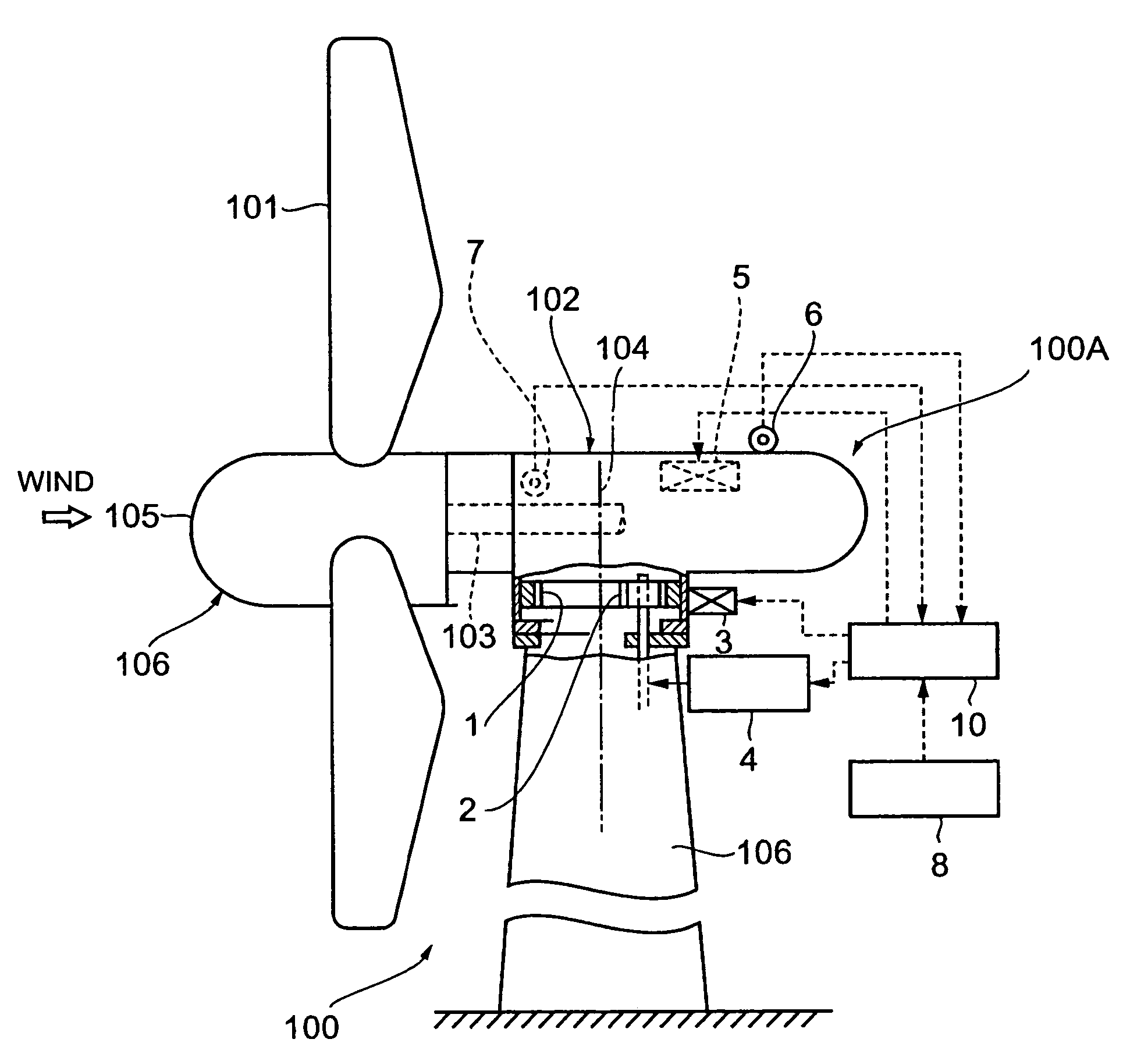
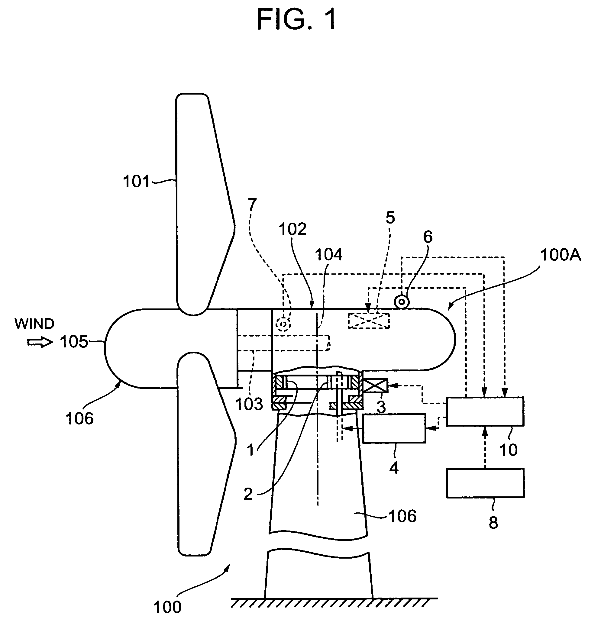
[0068]Referring to FIG. 1 showing the present invention, reference numeral 100 is an upwind type wind turbine. A rotor 105 provided with a plurality of blades 101 is located in the front part of a nacelle 102, (i.e. forward of the axis of rotation 104 of the nacelle 102) which is supported on a support 106. The rotor 105 is allowed to be rotated by the force of wind, and a driven machinery such as an electric generator contained in the nacelle 102 is driven via a main shaft 103 connected to the rotor 105 owing to the rotation force effected by the blades 101.

[0069]A plurality of blades 101 are attached to the rotor 105 on the periphery at a constant spacing. The pitch angle of each blade 101 is changeable by means of a pitch control means (not shown in the drawing) Variable pitch mechanisms are disclosed in Japanese Patent Application Publication No. 5-149237 and No. 7-4333, etc. Here will be explained a variable pitch angle mechanism referring to FIG. 15. A servomotor 312 for contr...

second embodiment

[0111]Next, the operation in the case of the second embodiment will be described with reference to FIG. 6 to FIG. 10.

[0112]In normal operation, yaw control is performed by releasing or applying the yaw brake 3 and motor brake. To be more specific, the yaw control (azimuth control) of the wind turbine proper 100A comprising the blades 101, rotor 105, and nacelle 102 is performed as follows; The nacelle 102 is fixed in an upwind position so that the blades 101 are positioned in the upstream position of the axis of rotation 104 of the nacelle, when the angle deviation between the wind direction detected by a wind direction detector and the bearing direction of the nacelle position is larger than a predetermined angle. The yaw brake 3 is then released to allow the nacelle to rotate in a horizontal plane by the predetermined angle around the axis of rotation 104 in correspondence with the wind direction, and then the yaw brake 3 is applied to fixate the wind turbine proper in the positio...


PUM


Abstract

A structure of an upwind type wind turbine and the operating method thereof capable of preventing the occurrence of damage of the blades by evading excessive irregular loads from acting on the blades in the slanting direction in the event of power failure when strong wind blows, are provided.In the upwind type wind turbine having a nacelle supported for rotation on a support, the nacelle is rotated to a downwind position by rotating it by 180° from a normal upwind position and kept in stand-by condition at a downwind position when detected wind speed is higher than the predetermined cutout wind speed, which is the reference wind speed for shifting to an idle operation state. When the detected wind speed is higher than the DWSS wind speed determined based on the maximum permissible instantaneous wind speed, the nacelle is rotated from an upwind position to a downwind position and the yaw brake is released.

Description

FIELD OF THE INVENTION[0001]The present invention is applied to a wind turbine generator and relates to an upwind type wind turbine having a rotor with a plurality of blades attached in the front part of a nacelle supported for rotation on a support, the rotor being rotated by wind force to drive a driven machinery such as a generator via a rotor shaft, and the operating method thereof.BACKGROUND OF THE INVENTION[0002]A wind turbine power plant having high capacity of generating electric power by installing a plurality of wind turbine electric power generator units each of which utilizes the rotation force generated by applying wind force to a plurality of blades to drive a generator via the rotor shaft, is constructed at high elevation such as the top of a hill or mountain or at a place such as above the sea where high wind velocity can be received. The generator set is generally controlled by adjusting the pitch angle of blades connected to the wind turbine rotor for keeping requi...

Claims


Application Information

Patent Timeline
Patent Type & Authority Patents(United States)
IPC IPC(8): F03D9/00H02P9/04F03B15/06F03B7/00H02H7/06H02P9/00H02P11/00F03B9/00F03D7/00F03D7/02F03D7/06F03D1/02F03D7/04
CPCF03D1/025F03D7/0204F03D7/0208F03D7/0244F03D7/0268F03D7/0276F03D7/042Y02E10/723F03D9/11F03D9/25F03D9/30F03D9/32F03D13/20F03D80/00Y02E10/72Y02E10/728Y02E70/30
Inventor SHIBATA, MASAAKIFURUKAWA, TOYOAKIHAYASHI, YOSHIYUKIYATOMI, YUUJITSUTSUMI, KAZUHISA
Owner MITSUBISHI HEAVY IND LTD
Why Eureka
Try Eureka