Communication network

Active Publication Date: 2008-10-14
NOKIA TECHNOLOGLES OY
View PDF23 Cites 0 Cited by
  • Summary
  • Abstract
  • Description
  • Claims
  • Application Information

AI Technical Summary

Benefits of technology

[0013]This provides the advantage of allowing channel allocation between full speech rate and half speech rate to be performed dynamically in accordance with system capacity requirements. This minimizes the risk of channel blocking due to system capacity limitations. Pr

Problems solved by technology

As system capacity varies with time this may result in the capa

Method used


Image

  • Communication network
  • Communication network

Examples


Embodiment Construction

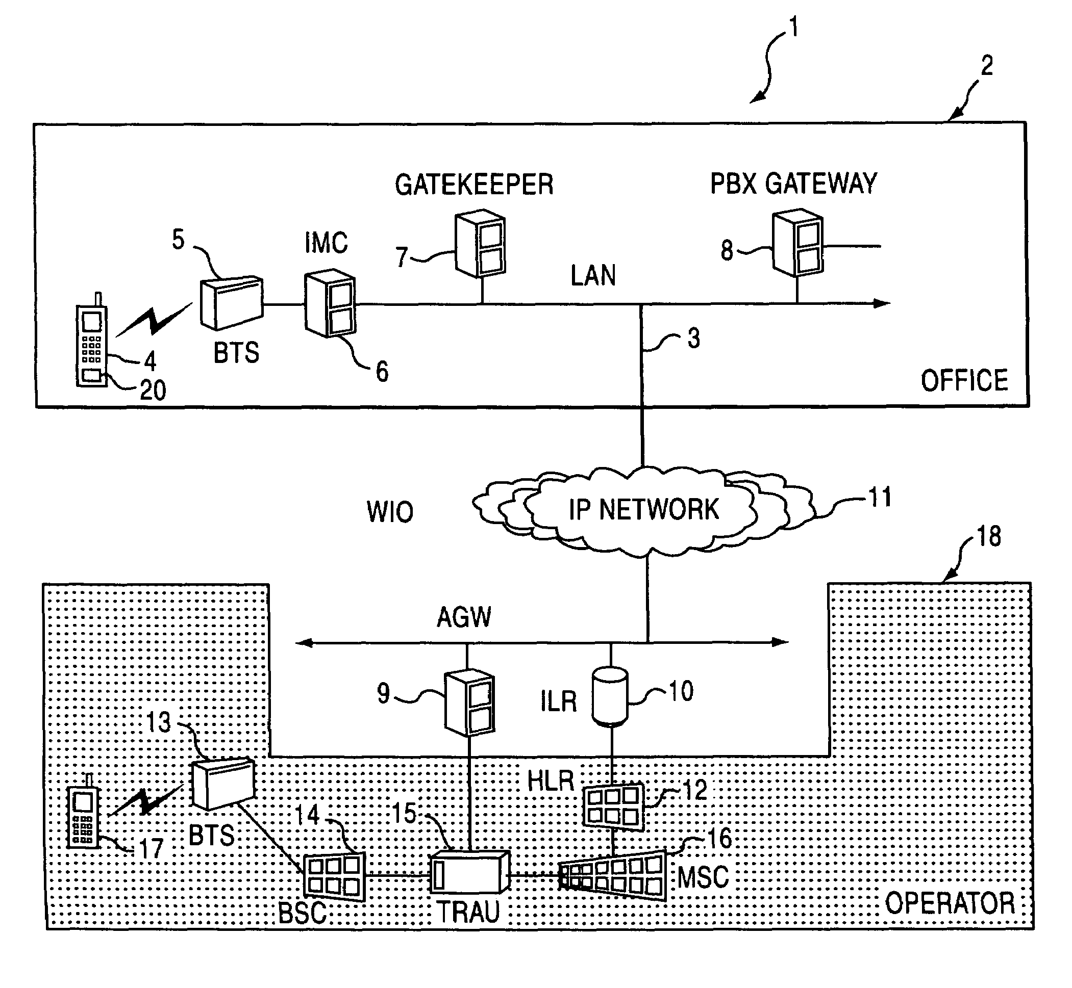
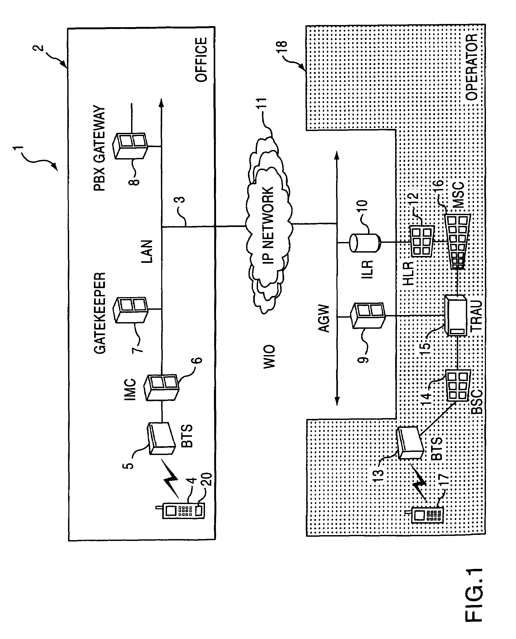
[0023]FIG. 1 shows a communication system 1 comprising a wireless intranet office (WIO) network 2 coupled to a GSM operator network 18.

[0024]The WIO network 2 is based around an office's local area network 3 (LAN), which is used as a platform for carrying, via IP traffic, wireless data communication received from a radiotelephone 4, thereby allowing IP telephony. Typically the IP telephony over the LAN 3 will be in accordance with the ITU H.323 standard.

[0025]The mobile GSM operator network 18 is based on a conventional cellular GSM network. The WIO network 2 comprises a base transceiver station 5 (BTS), a local area network 3 (LAN), an intranet mobile cluster 6 (IMC), a gatekeeper 7, a public branch exchange (PBX) gateway 8, an A-interface gateway 9 (AGW) and an intranet location register 10 (ILR).

[0026]The BTS 5 is for communicating with a plurality of radiotelephones 4 (of which only one is shown) over respective communication channels in the WIO environment. The air interface be...


PUM


Abstract

A network for communicating with a plurality of radiotelephones via respective communication channels over timeslots on a carrier, wherein the channels can operate at a first or second data rate such that a timeslot on the carrier can transmit a single communication channel operating at the first data rate or two communication channels operating at the second data rate, the network comprising a controller responsive to a predetermined condition for initiating a change in the data rate of two channels transmitted on separate timeslots from the first data rate to the second data rate.

Description

BACKGROUND OF THE INVENTION[0001]1. Field of the Invention[0002]This invention relates to a communication network, in particular a communication network for dynamically allocating channels.[0003]2. Description of the Prior Art[0004]The popularity of cellular communication is, in part, due to its ability to allow a relatively large number of users to establish communication links over a relatively limited bandwidth. However, as the popularity of cellular communication continues to increase, the demands for increased capacity continue.[0005]Time Division Multiple Access (TDMA) cellular communication systems increase capacity by splitting a carrier frequency into a plurality of timeslots, thereby allowing a plurality of communication channels to be established over the same carrier frequency.[0006]To allow speech data to be transmitted in a timeslot, the speech data is compressed using a codec.[0007]To further increase capacity certain TDMA standards, for example GSM, allow the use of ...

Claims


Application Information

Patent Timeline
IPC IPC(8): H04B7/212H04J3/16H04L12/66H04Q7/20H04W28/22
CPCH04W28/22
Inventor HANNINEN, TIMORAUTIOLA, MARKKUSIIK, TAPIOUOSUKAINEN, PETRIHONKALA, HANNURISSANEN, JARI PEKKANARVANEN, KAIMICKOS, ROY
Owner NOKIA TECHNOLOGLES OY
Why Eureka
Try Eureka