System and method for problem determination using dependency graphs and run-time behavior models

a dependency graph and run-time behavior technology, applied in the field of system and method for determining the source of problems, can solve the problems of reducing the number of components to be investigated by the system administrator, reducing the number of resources, and reducing the time it takes

Inactive Publication Date: 2008-10-14
GLOBALFOUNDRIES INC
View PDF12 Cites 42 Cited by
  • Summary
  • Abstract
  • Description
  • Claims
  • Application Information

AI Technical Summary

Benefits of technology

[0006]An exemplary aspect of the invention addresses the scalability problem by automatically and dynamically setting appropriate thresholds on internal components, thus reducing the number of events and the number of components that are investigated by a human administrator or any problem determination (PD) program.
[0009]Accordingly, a problem determination system and method is described that automates and tightens threshold assignments on individual components so that spurious events are not generated and components that are very unlikely to be root-causes are not investigated. An exemplary aspect of the invention reduces the number of components to be investigated and, therefore, the time required for problem determination.
[0011]An important advantage of using this solution is a reduction in the time it takes to perform root cause analysis than in current systems. This is because the use of dependency information coupled with the behavior thresholds values (or limits) significantly reduces the number of resources that an administrator needs to examine for possible faults. This reduction in diagnosis time results in operational cost savings. A further advantage is that the problem determination system and method of this invention is more scalable than existing solutions.

Problems solved by technology

Existing solutions to determining the source of the problem are notoriously slow and labor intensive.
Since per-component and per-metric thresholds are hard to configure for a human administrator, several unnecessary events are typically generated in such a system, stressing the CE.
In large customer environments, where resources may number in the thousands and tens of thousands, the number of events generated is often overwhelming for the system to analyze and the number of components to be investigated by the system administrator can be quite high.
This results in costly delays in identifying the root cause thereby resulting in an expensive problem determination and remediation process.

Method used


Image

  • System and method for problem determination using dependency graphs and run-time behavior models
  • System and method for problem determination using dependency graphs and run-time behavior models
  • System and method for problem determination using dependency graphs and run-time behavior models

Examples


Embodiment Construction

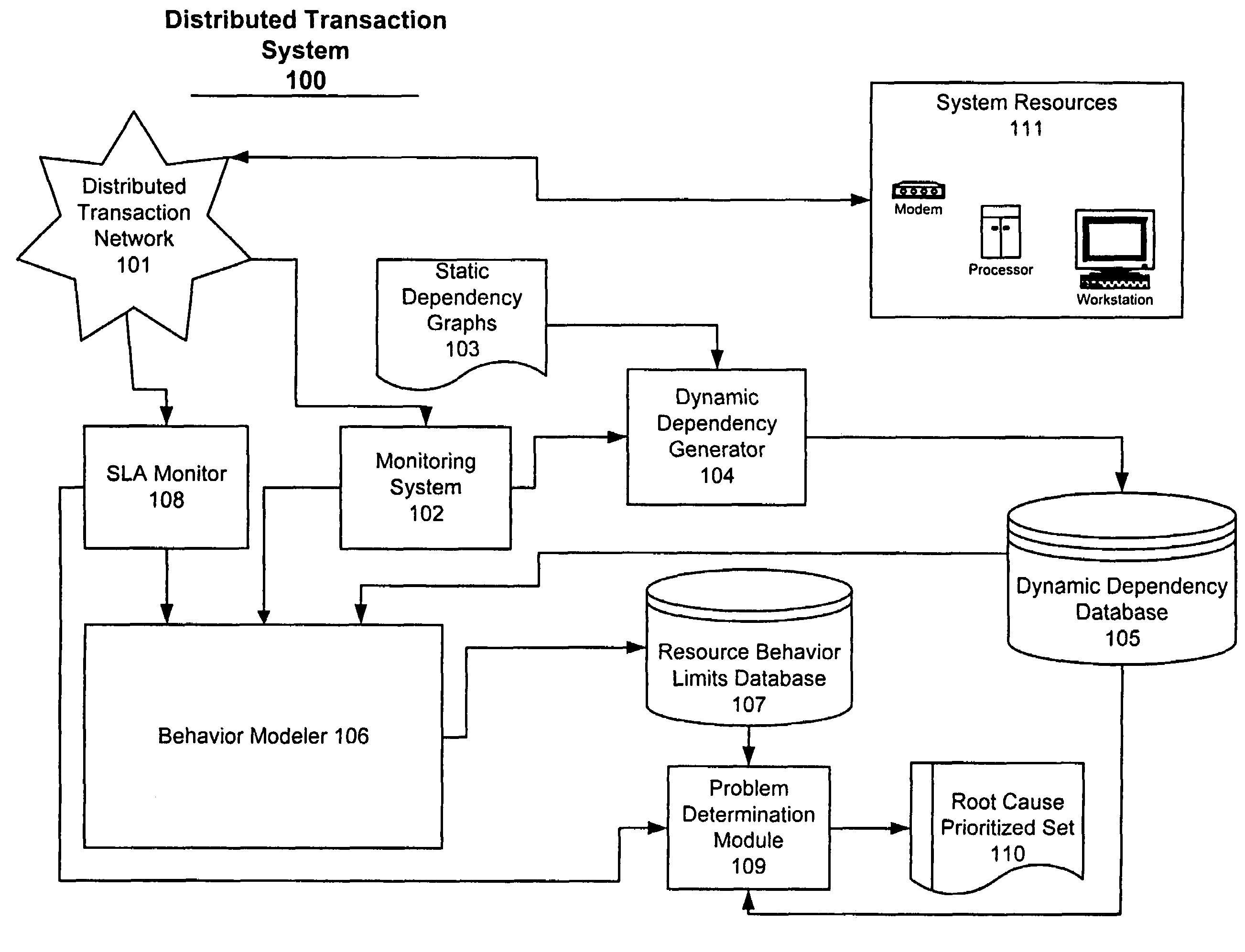
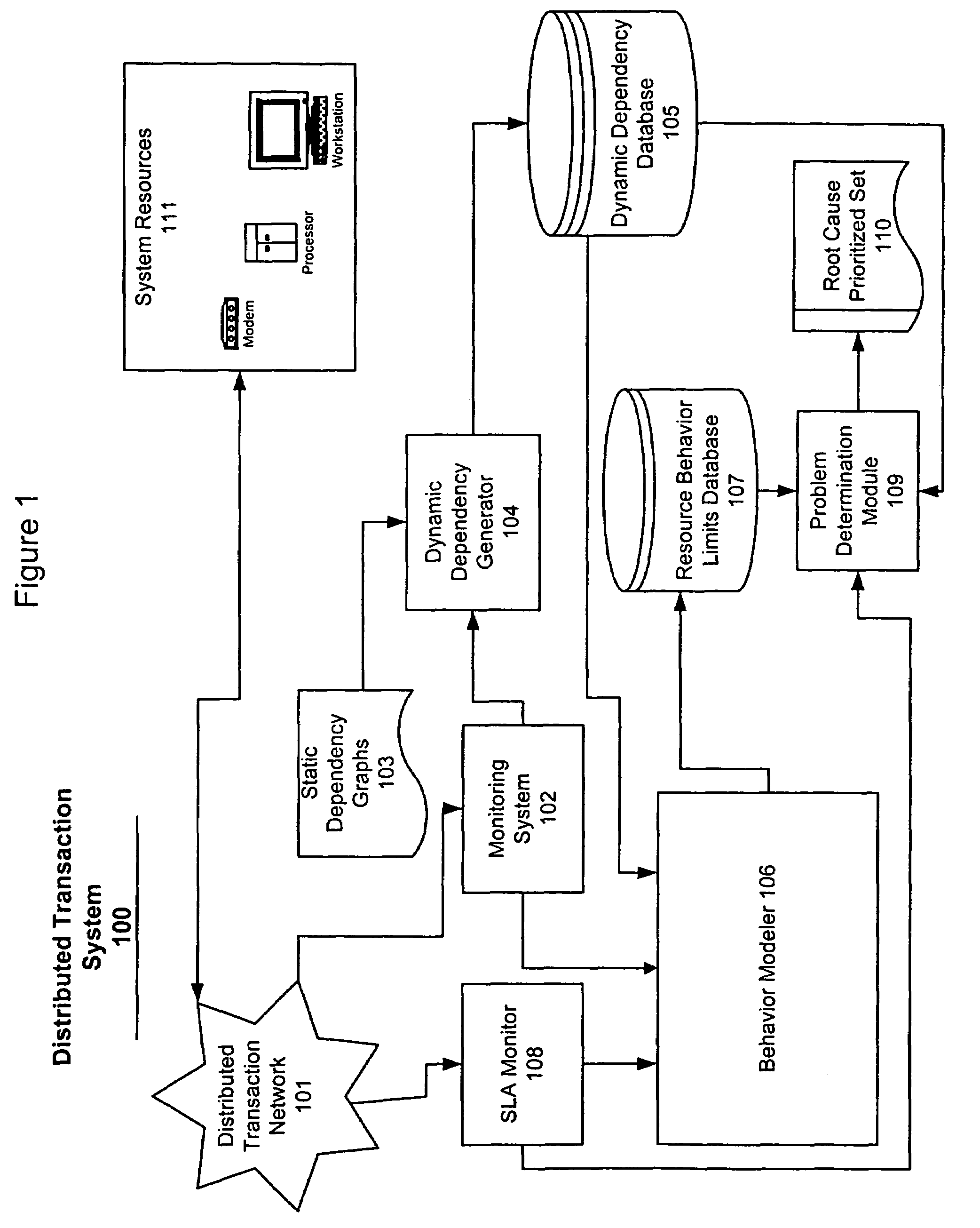
[0017]Referring now to the drawings, and more particularly to FIG. 1, there is shown a schematic of a Problem Determination (PD) system. A distributed transaction system 100 includes a distributed transaction network 101 and systems resources 111. The systems resources 111 are shown in FIG. 1 to include but are not limited to modems, processors and workstations but may also include numerous other types of typical I / T resources (e.g., HTTP servers, load balancers, application servers, database servers, caches, storage, transmission systems, etc.). Monitoring data from the distributed transaction system 100 is provided to the Service Level Agreement (SLA) monitor 108 and the monitoring system 102 of the invention via the distributed transaction network 101. The monitoring system 102 periodically polls each of the resources of the distributed transaction system 100 to obtain values of metrics which have been defined for the resources. The specific metrics that are measured for a given ...


PUM


Abstract

A problem determination system and method reduces the time and effort required by system administrators to trouble shot transaction processing difficulties in a large distributed I / T environment by monitoring system component performance and computing operational performance threshold limits based on dependency graphs for the system. Using this data, a prioritized list of suspect components for the I / T system is generated.

Description

BACKGROUND OF THE INVENTION[0001]1. Field of the Invention[0002]The invention generally relates to a system and method for performing problem determination in large distributed information technology (I / T) environments and, more particularly, to a system having a set of algorithms and processes that analyze system dependency graphs, set acceptable operating limits, and create priority sequences of possible faulty resources for use by a system administrator to investigate the problem.[0003]2. Background Description[0004]An example of a large distributed I / T environment is a multi-tier e-business system which is supported by an infrastructure consisting of the following subsystems connected by local and wide area networks: web based presentation services, access services, application business logic, messaging services, database services and storage subsystems. One of the major challenges for administrators of such systems is to pinpoint the root-cause when a problem is discovered at a...

Claims


Application Information

Patent Timeline
Patent Type & Authority Patents(United States)
IPC IPC(8): G06F11/00
CPCG06F11/0709G06F11/079G06F11/3409G06F11/3452G06F2201/81G06F2201/87
Inventor AGARWAL, MANOJ K.APPLEBY, KARENGUPTA, MANISHKAR, GAUTAMNEOGI, ANINDYASAILER, ANCA
Owner GLOBALFOUNDRIES INC
Why Eureka
Try Eureka