Method of evaluating a disc brake rotor

a disc brake and rotor technology, applied in the direction of force/torque/work measurement apparatus, electrical/magnetic measuring arrangement, structure/machine measurement, etc., can solve the problems of excessive rotor wear and other undesirable effects, and affecting the accuracy of the tes

Active Publication Date: 2008-10-21
ROBERT BOSCH CORP +1
View PDF8 Cites 28 Cited by
  • Summary
  • Abstract
  • Description
  • Claims
  • Application Information

AI Technical Summary

Benefits of technology

[0011]An advantage of the present invention is that rotor irregularities may be pinpointed and, for example, a high spot on a rotor caused by a cast rotor cooling too fast or a die imperfection can be traced back to its cause in the die that cast it.
[0012]Another advantage is wheel speed compensation which provides equiangularly spaced samples.
[0013]A further advantage is unique numerical processing of the test data and presentation of the results.
[0014]A still further advantage is that data processing employs mathematical functions based on spline interpolations and can account for speed variations in the rotation of the rotor or wheel during measurement.
[0015]Another unique feature of the invention is that rotor geometry may be represented in a three dimensional view indicating the form error's magnitude and location on the rotor.
[0016]In the present invention, non-contact displacement capacitive sensors supply analog signals to signal conditioning circuitry which scales

Problems solved by technology

However excessive wobble or other deviations from opposed flat surfaces orthogonal to the wheel axis can cause brake chatter, excessive rotor wear and other undesirable results.
Even under controlled laboratory conditions, speed variations may sometimes

Method used


Image

  • Method of evaluating a disc brake rotor
  • Method of evaluating a disc brake rotor
  • Method of evaluating a disc brake rotor

Examples


Embodiment Construction

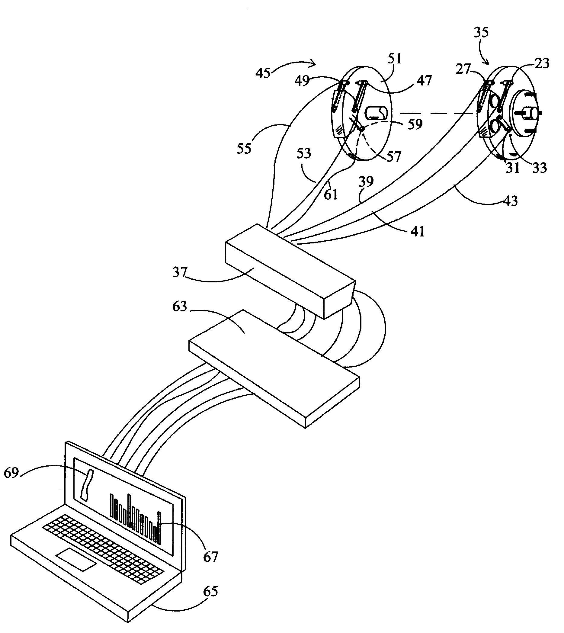
[0024]FIG. 1 is a schematically illustration of a portion of a vehicle wheel and disc brake mechanism wherein a rotor 11 is fixed to and rotatable with a vehicle wheel. The tire and rim of the wheel have been removed from the hub and lugs. A caliper 13 associated with an anchor has retains a pair of rotor engaging friction surfaces or pads located on opposite sides of the rotor 11. The pads are urged into engagement with opposed sides of faces 17 and 19 of the rotor 11 by a pair of hydraulic cylinders (pistons) such as 15. An arm 21 fixed to the caliper housing spans the rotor 11 to support a sensor 23 and probe 25 in a position closely adjacent the rotor surface 17. A similar sensor 27 is similarly mounted closely adjacent the opposite rotor surface 19 in alignment with the sensor 23. The sensors may be mounted to any other convenient non-rotating vehicle member as desired. The sensor probes such as 25 engage the surfaces and the distance between the probes is the thickness of the ...


PUM


Abstract

A method for determining local departures of opposed friction surfaces that are spaced apart in parallel planes normal to the axis of the rotor. Displacement sensing probes are placed in opposing alignment adjacent the friction surfaces and rotor is spun. Instantaneous distances from each probe to the friction surfaces is made by repetitively sampling and converting the sample distances into digital form. The differences between contemporaneous sample distances are computed to determine rotor thicknesses and displayed. An analog measure of the instantaneous angular rotor position is provided for each instantaneous angular position. The angular rotor position and distance measures are correlated and the angular rotor position sample converted to digital form. While the time interval between successive distance samples is constant the rotor angular velocity may vary during a revolution and spline-based interpolation between successive distance samples is performed to obtain to obtain a representation of equiangularly spaced sample values.

Description

[0001]The present invention relates to a method of evaluating dimensional variations on braking surfaces of a rotor for a disc brake.BACKGROUND OF THE INVENTION[0002]A braking system for a vehicle includes a flat disc or rotor that is fixed to and rotatable with an associated vehicle wheel and a caliper that is fixed to the vehicle chassis spans the rotor. A pair of friction surfaces or pads retained by the caliper are urged by pressurized fluid acting on a piston and the caliper housing into engagement with opposed rotor faces to effect a brake application. When the pressurized fluid is released the resiliency of a seal associated with the piston moves the piston and caliper housing to provides sufficient running clearance between the pads and the rotor. In some instances, a controlled rotor wobble or run-out is desirable to supplement the restorative force of the resilient seals to retract pads from the rotor after a braking event. However excessive wobble or other deviations from...

Claims


Application Information

Patent Timeline
IPC IPC(8): G01M19/00G01M99/00
CPCG01B5/0028G01B7/08
Inventor MCNAUGHTON, ROBERT J.MALBURG, MARK
Owner ROBERT BOSCH CORP
Why Eureka
Try Eureka