Six-axis force sensor

a six-axis force sensor and sensor technology, applied in the direction of force/torque/work measurement apparatus, racket sports, force measurement, etc., can solve the problems of complicated leg machining process, difficult to provide a small robot, and high cost of shear strain gauges, so as to achieve easy generation of deflection, improve the sensitivity of six-axis force sensors to force and a moment, and avoid the effect of assembling process

Active Publication Date: 2008-10-21
FANUC LTD
View PDF7 Cites 47 Cited by
  • Summary
  • Abstract
  • Description
  • Claims
  • Application Information

AI Technical Summary

Benefits of technology

[0008]It is therefore an object of the present invention to provide a low-cost six-axis force sensor which has a simple structure and can easily be made smaller.
[0011]In the six-axis force sensor, the first single-axis-type strain gauge attached to the cross beam is preferably disposed at the middle between two longitudinal ends of the cross beam on the surface of the cross beam facing the side opposite to the vertical beam. The largest deflection and strain of the cross beam are generated at the middle of the cross beam in the longitudinal axis direction thereof. Therefore, attachment of the six-axis force sensor to the middle of the cross beam in the longitudinal axis direction thereof can improve strain detection sensitivity. The first single-axis-type strain gauge attached to the cross beam may be disposed at one or both of two longitudinal ends of the cross beam on the surface of the cross beam facing the vertical beam.
[0013]Preferably, the vertical beam of each leg is formed with an opening extending through the vertical beam in a radial direction of the circle. In the case where the vertical beam is thus formed with the opening, a deflection is easily generated on the vertical beam in a circumferential direction of the circle or in a tangential direction of a circle. As a result, sensitivity of the six-axis force sensor to a force and a moment can be improved.
[0014]Preferably, the pair of members and the legs are integrated with each other. In the case where the pair of members and the legs are integrated with each other, an assembling process can be advantageously eliminated.
[0015]Preferably, the single-axis-type strain gauge is a semiconductor-type strain gauge. The semiconductor-type strain gauge can detect strains with a sensitivity higher than a metal foil gauge or the like. Therefore, when a semiconductor-type strain gauge is used as a single-axis-type strain gauge, the force detection resolution of the six-axis force sensor can be improved. As a smaller strain can be detected, a smaller deflection of the legs may be detected. As a result, the strength of the legs can be improved, and a six-axis force sensor having a stronger structure can be provided.
[0016]The simple shape of the T-shaped leg makes it easier to machine the legs by cutting machining or wire electric discharge machining, thereby contributing to a decreased manufacturing cost. A single-axis-type strain gauge is smaller and cheaper than a shear strain gauge and, even if the T-shaped leg is made smaller, the machining of the leg is still easy. Therefore, a small six-axis force sensor can be provided at low cost.

Problems solved by technology

Presence of these pockets complicates a machining process for the leg and makes it difficult to provide a small robot.
Further, the shear strain gauge is more expensive than a single-axis-type strain gauge.

Method used


Image

  • Six-axis force sensor
  • Six-axis force sensor
  • Six-axis force sensor

Examples


Embodiment Construction

[0023]Several preferred embodiments of the present invention will be described below with reference to the accompanying drawings.

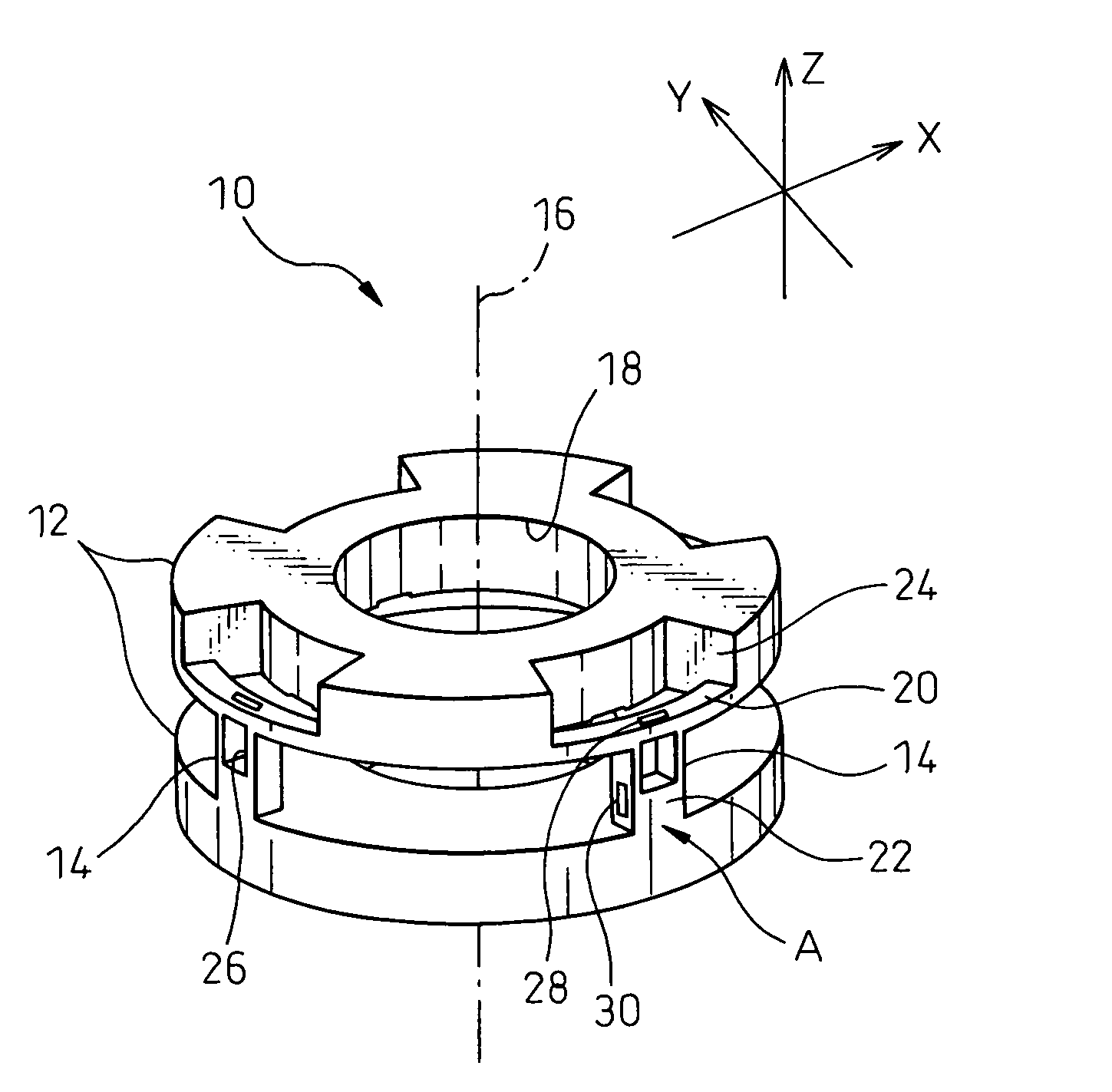
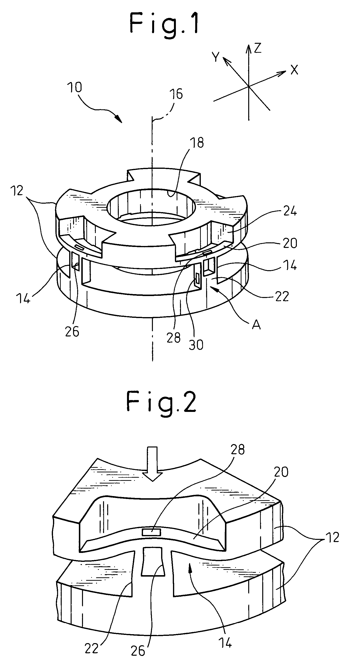
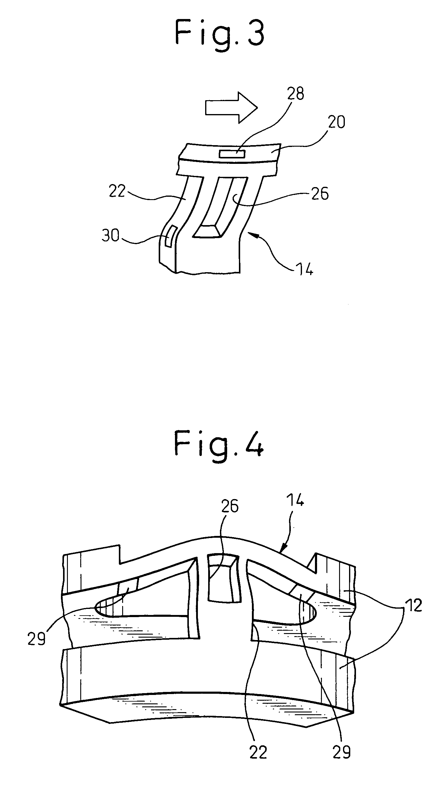
[0024]FIG. 1 is a perspective view of a six-axis force sensor according to a first embodiment of the present invention. Referring to FIG. 1, a six-axis force sensor 10 includes a pair of disc-shaped members 12 disposed in opposed relation to each other, and legs 14 disposed between the pair of disc-shaped members 12 and connecting the two disc-shaped members 12.

[0025]The pair of disc-shaped members 12 are arranged so that the center axes 16 thereof are aligned in one straight line. The pair of disc-shaped members 12 are mounted to different structures (not shown) and, for example, are positioned at both sides of a joint of a robot. The disc-shaped member12 is formed at the center thereof with a through-hole 18 extending along the center axis 16 thereof. In the through-hole 18, a portion connecting the different structures such as parts of a joint of a robo...


PUM

PropertyMeasurementUnit
circumferenceaaaaaaaaaa
forcesaaaaaaaaaa
external forceaaaaaaaaaa

Abstract

A six-axis force sensor includes a pair of members, and at least three legs scatteringly disposed between the pair of members on the periphery of the members. Each leg includes a T-shaped leg consisting of a cross beam supported at both ends thereof by one of the pair of members and extending on the periphery of the member in a circumferential direction, and a vertical beam extending from the center of the cross beam to a direction perpendicular to the cross beam and connected to the other of the pair of members. The strains on the legs are detected by first single-axis-type strain gauges and second single-axis-type strain gauges. A first single-axis-type strain gauge is attached to a surface of the cross beam facing the side opposite to the vertical beam or a surface of the cross beam facing the vertical beam, so as to be able to detect a strain generated in the cross beam in a longitudinal axis direction thereof, and a second single-axis-type strain gauge is attached to a side surface of the vertical beam facing in a circumferential direction, so as to be able to detect a strain generated in the vertical beam in a longitudinal axis direction thereof.

Description

BACKGROUND OF THE INVENTION[0001]1. Field of the Invention[0002]The present invention relates to a six-axis force sensor which can measure the forces in the directions of the X-, Y- and Z-axes and the moments around the X-, Y-, and Z-axes.[0003]2. Description of the Related Art[0004]For example, when an external force is applied to a front end of a robot arm, a load acts on a wrist of the arm. This load consists of forces in the directions of the X-, Y-, and Z-axes, and moments around the X-, Y-, and Z-axes. In order to measure such forces and moments, it is common to use a force sensor of the type which measures loads using the strain generated in a structure due to a load.[0005]Japanese Unexamined Patent Publication No. 8-122178 discloses an example of such a force sensor. The six-axis force sensor disclosed in Japanese Unexamined Patent Publication No. 8-122178 includes a hollow cylindrical sensor body, and three or four legs built in the sensor body. Each leg includes a first ar...

Claims


Application Information

Patent Timeline
Patent Type & Authority Patents(United States)
IPC IPC(8): G01L5/16
CPCG01L5/161G01L5/162
Inventor SAKANO, TETSURO
Owner FANUC LTD
Why Eureka
Try Eureka