
Portable field anesthesia machine and control therefore

a portable, anesthesia machine technology, applied in the field of anesthesia machines, can solve the problems of substantial insensitivity of the machine to shock and vibration, and achieve the effects of minimizing the dangers of manual compensation and constant vigilance, minimizing internal resistance, and less setup and overhead maintenan

Inactive Publication Date: 2008-10-21
IZUCHUKWU JOHN I
View PDF42 Cites 66 Cited by
  • Summary
  • Abstract
  • Description
  • Claims
  • Application Information

AI Technical Summary

Benefits of technology

The machine enables reliable and precise anesthesia delivery in various environments, reducing logistical overhead and improving the capability for rapid, effective treatment in emergency and field surgical situations, including combat and disaster scenarios, by being lightweight, easy to set up, and compatible with standard monitoring systems.

Problems solved by technology

The machine is substantially insensitive to shock and vibration.

Method used


Image

  • Portable field anesthesia machine and control therefore
  • Portable field anesthesia machine and control therefore
  • Portable field anesthesia machine and control therefore

Examples


first embodiment

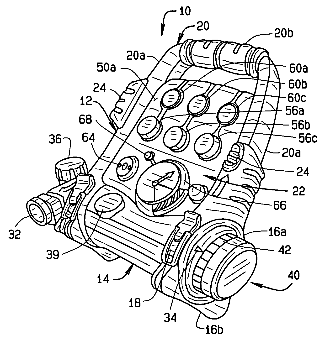
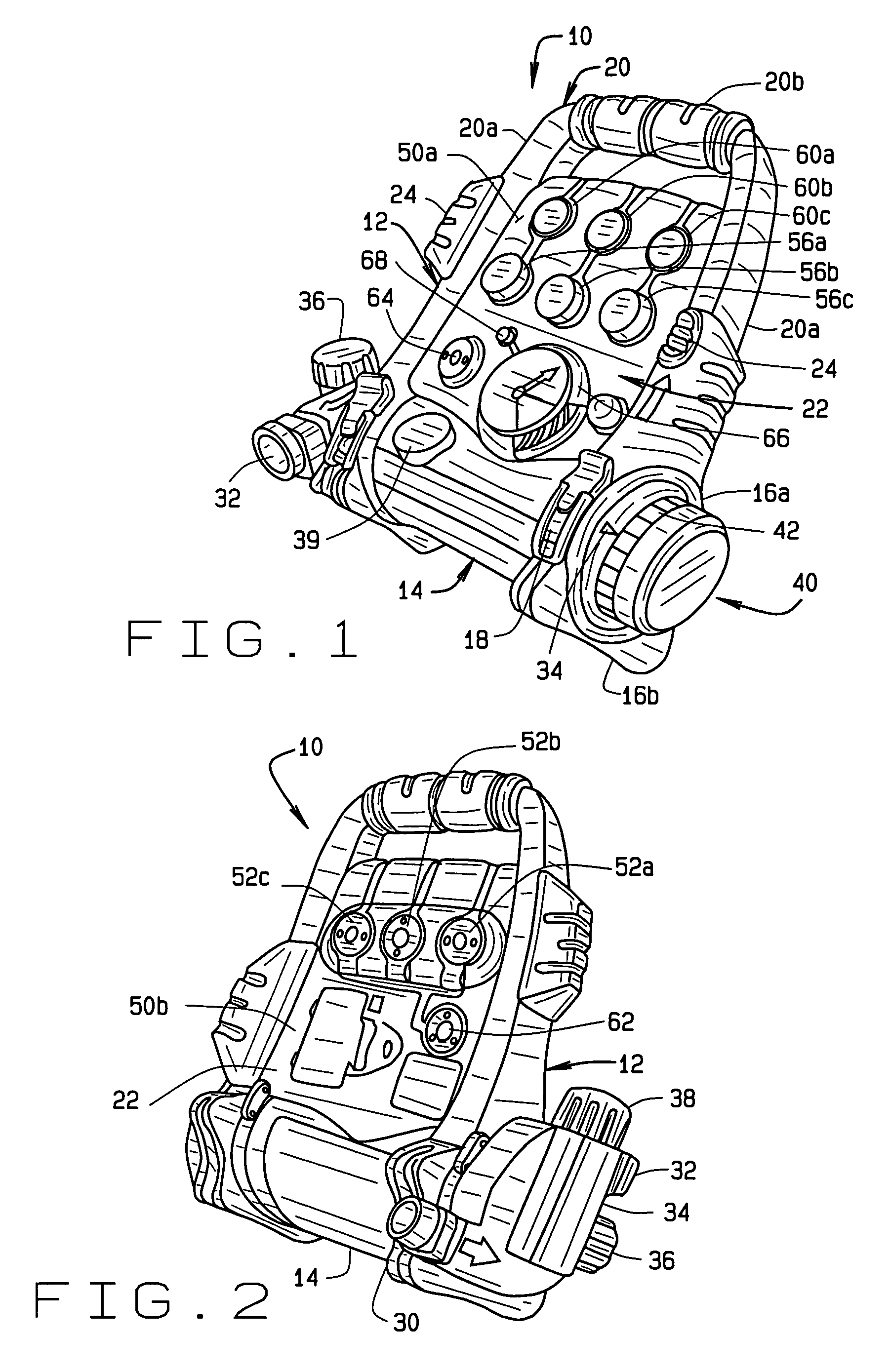
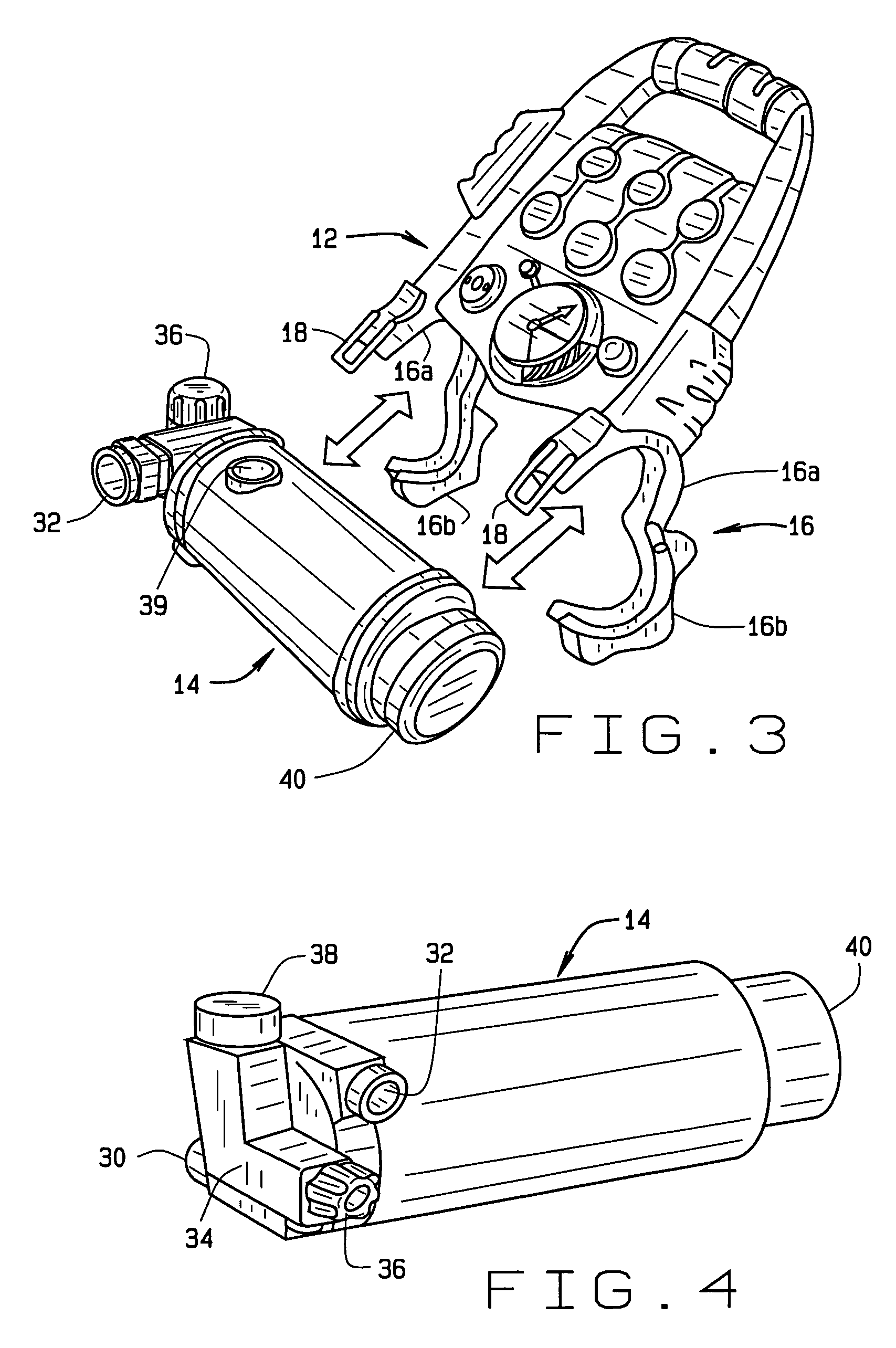
[0063]An illustrative first embodiment of an anesthetic machine 10 of the present invention is shown generally in FIGS. 1-3. The anesthetic machine 10 comprises a chassis 12 which removably receives a vaporizer 14. As seen best in FIG. 3, the chassis 12 includes, at the bottom thereof, a cradle 16 in the form of a clasp or clamp comprising a fixed portion 16a and a movable portion 16b hingedly connected to the fixed portion at one end thereof. The fixed and movable portions of the clasp included matable latches 18 at their free ends which cooperate with each other to maintain the clasp portions together to thereby hold the vaporizer 14 to the chassis 12. The clasp latches 18 can be opened to allow for the vaporizer to be removed from the chassis.

[0064]A generally U-shaped handle 20 extends upwardly from the chassis. The handle 20 includes arms 20a extending upwardly from the clasp fixed portion 16a and a gripping portion 20b extends between the arms 20a at the tops thereof. A panel ...

third embodiment

[0079]Illustrative views of the anesthesia machine are shown in FIGS. 10-13. Like the anesthesia machine 10, the machine 210 comprises a chassis 112 which removably receives the vaporizer 14′. The chassis 212 is concavely curved, as at 212a and 212b to define dual placement feet for the machine 210. The feet can be made from, or covered with, a non-slip rubber.

[0080]A cradle 216 is formed in the chassis to receive the vaporizer 14′. As seen in FIG. 12, the chassis 212 includes a forward section 213 and a back section 215. The chassis back section 215 includes a channel defined by a curved surface 215a which is shaped to receive the vaporizer 14′. As with the anesthesia machine 110, the chassis back section 215 includes ports which receive the inlet and outlet tubes 30′ and 32′ of the vaporizer 14′. The side walls of the chassis back section 215 have cutouts 215b forms therein. The cutouts 215b on the opposite side walls are sized and shaped to receive the vaporizer control dial 40′ ...


PUM


Abstract

A portable anesthetic machine comprises a chassis having a cradle which removably receives a vaporizer, a control panel and a support member. The control panel and support member are pivotal relative to each other to selectively change the machine between carrying and use configurations. The control panel includes a gas flow path having gas inputs connectable to sources of carrier gases, a manifold which combines the gases, a carrier gas outlet and inlet connectable to the vaporizer input and outlet, respectively, a common gas port, and flow control devices to control the carrier gas flow rate and to control the anesthetic and carrier gas mixture. A controller is also provided which controls the flow of gas into and around the vaporizer to maintain a substantially constant concentration of anesthetic agent in the gas stream delivered to the patient without the need to adjust the flow of gases from the gas supply sources.

Description

CROSS-REFERENCE TO RELATED APPLICATIONS[0001]This application claims priority to U.S. Provisional Application No. 60 / 657,983 filed Mar. 2, 2005, entitled “Portable Field Anesthesia Machine And Control Therefore”, and which is incorporated herein by reference.STATEMENT REGARDING FEDERALLY SPONSORED RESEARCH OR DEVELOPMENT[0002]Not Applicable.BACKGROUND OF THE INVENTION[0003]This invention relates to anesthesia machines, and in particular, to anesthesia machines which are easily transportable.[0004]Anesthesia machines are well known in the art for use in anesthetizing humans as well as other animals for surgical purposes. Virtually all prior art anesthetic machines are intended to be fixedly mounted in a stable environment, such as in a hospital operating room. This is usually required by the design of the machine and especially the vaporizer in which the liquid anesthetic agent is contained. Should the anesthetic machine be jostled, or its attitude be changed such as by tilting or th...

Claims


Application Information

Patent Timeline
Patent Type & Authority Patents(United States)
IPC IPC(8): A61M16/00
CPCA61M16/0051A61M16/01A61M16/104A61M16/18A61M16/1015A61M16/12A61M16/22A61M2016/0027A61M2016/0039A61M2016/1035A61M2202/0208A61M2202/0283A61M2205/3358A61M2205/3372A61M2205/3389A61M2205/3584A61M2205/3673A61M2205/502A61M2205/52A61M2205/584A61M2230/04A61M2230/06A61M2230/10A61M2230/205A61M2230/30A61M2230/42A61M2230/432A61M16/101A61M16/024
Inventor IZUCHUKWU, JOHN I.
Owner IZUCHUKWU JOHN I
Learn More