Eureka AIR delivers breakthrough ideas for toughest innovation challenges, trusted by R&D personnel around the world.

Multimodality imaging phantom and process for manufacturing said phantom

a multi-modal imaging and phantom technology, applied in the field of multi-modal imaging phantoms, can solve the problems of no gold standard to assess the accuracy of imaging devices, no imaging technique is error free, and no phantoms

Inactive Publication Date: 2008-10-21
LINSTITUT DE RES & DEVS CLINIQUES DE MONTREAL +2
View PDF13 Cites 9 Cited by
  • Summary
  • Abstract
  • Description
  • Claims
  • Application Information

AI Technical Summary

Problems solved by technology

Even after calibration, no imaging technique is error free.
These real vessel phantoms had two limitations: first, the geometry of the artery was not known a priori, and thus, there was no gold standard to assess the accuracy of the imaging devices.
Second, the geometry of each artery was unique and could not be duplicated if the vessel was damaged.
The blood- and tissue-mimicking materials had X-ray, ultrasound and MRA properties close to those of blood and human tissues, but polyester resin was found to be a poor ultrasound and MRA tissue-mimicking material.
A drawback of this method is the absence of tissue-mimicking material around the vessel, which has implications in MRA and ultrasound images.
One limitation of stereolithography is that it only allows fabrication of rigid-wall phantoms, and the type of materials that can be used is limited.
Moreover, the lumen of the vessel is not perfectly smooth (Fahrig et al., 1999).
However, all of these patents describe apparatus and methods that are each limited to a single mode of imaging.

Method used


Image

  • Multimodality imaging phantom and process for manufacturing said phantom
  • Multimodality imaging phantom and process for manufacturing said phantom
  • Multimodality imaging phantom and process for manufacturing said phantom

Examples


Embodiment Construction

[0041]The present invention is directed to a multimodality imaging phantom for calibrating an imaging apparatus, and more preferably, the apparatus uses one of the following imaging modalities: ultrasonography, X-ray angiography, X-ray computed tomography and magnetic resonance imaging.

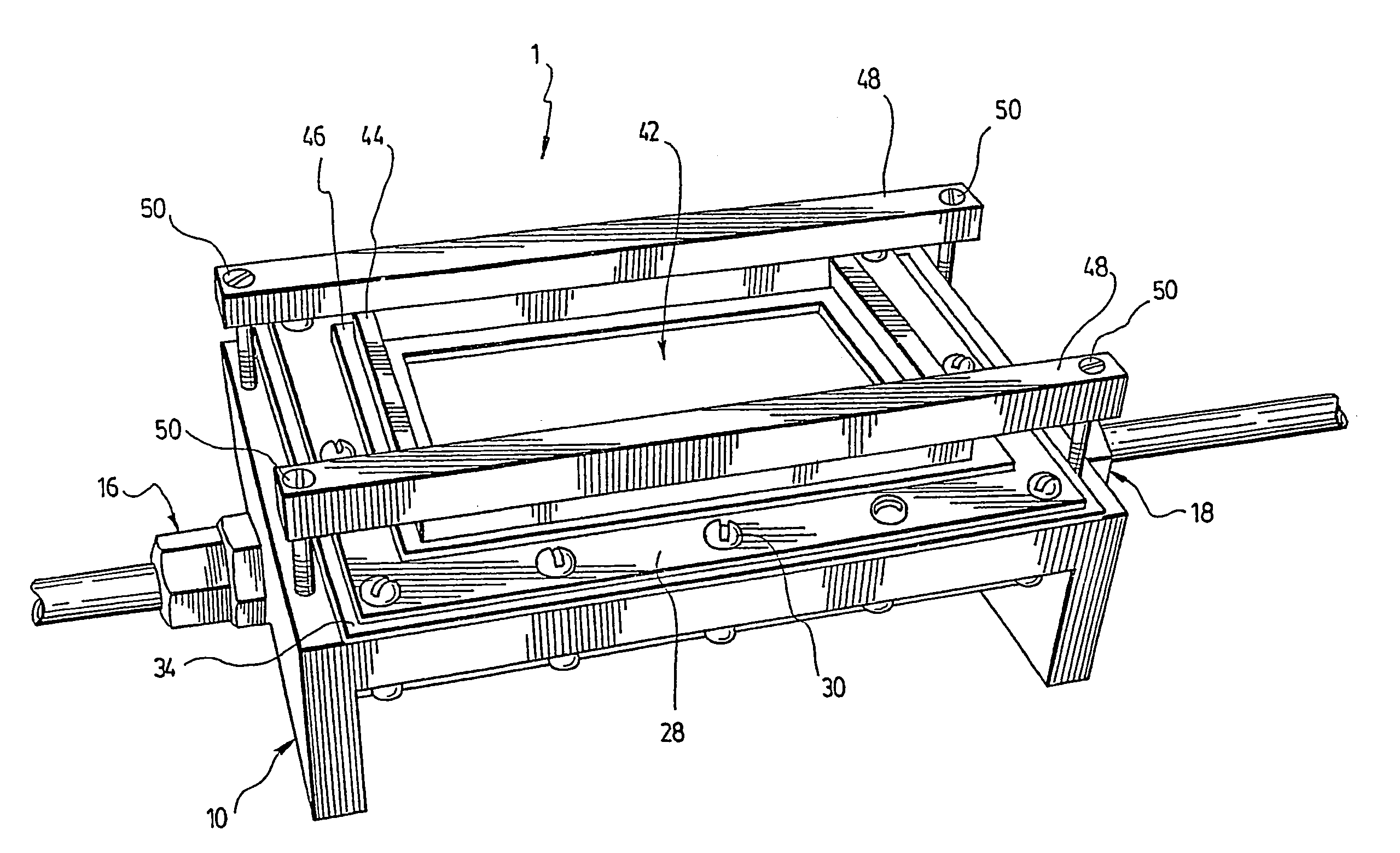
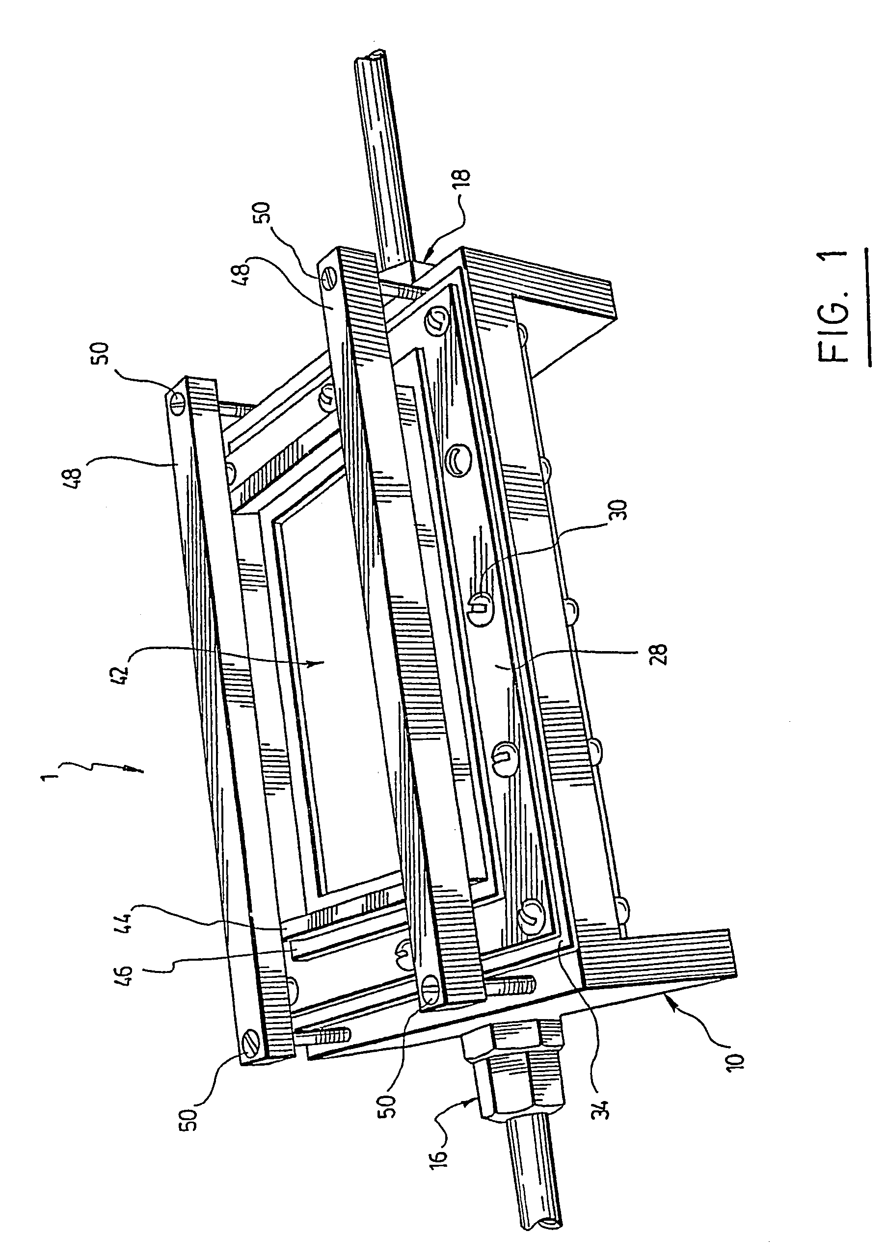
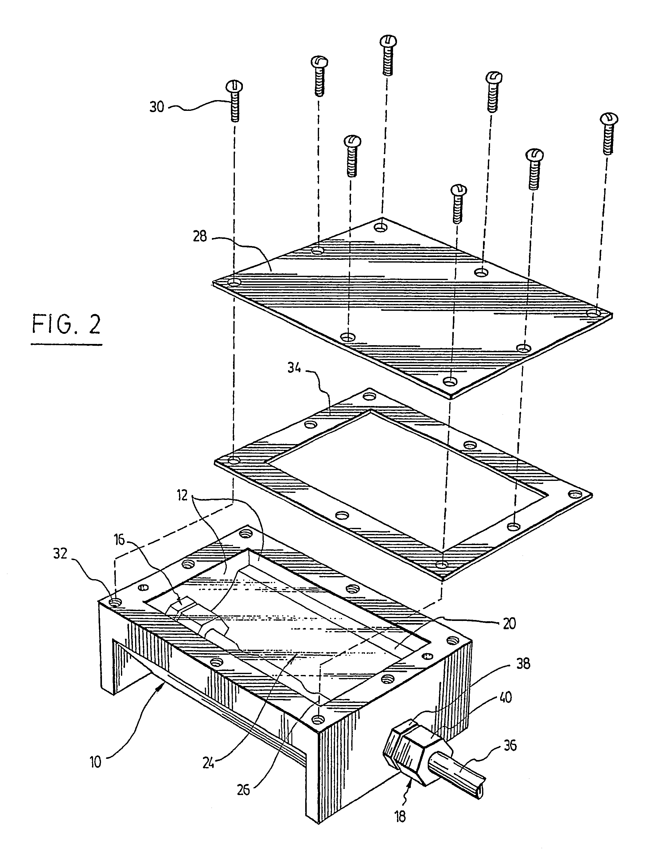
[0042]As shown in FIGS. 1, 2, 3, 4 and 11, the multimodality imaging phantom (1) comprises a container (10) having walls (12) allowing a use of the imaging apparatus (not shown) for imaging the interior (14) thereof. The walls (12) are provided with an inlet (16) and an outlet (18).

[0043]As shown in FIG. 4, the phantom (1) also comprises a first layer (20) of tissue mimicking material located in a portion of the interior (14) of the container (10). At least one marker (22) is embedded in the first layer (20). The markers (22) have an acoustic impedance that is 3 to 30 times higher than that of the first layer (20), an X-ray absorption coefficient that is 3 to 50 times higher than that of the first lay...


PUM


Abstract

A multimodality imaging phantom is disclosed which is useful for calibrating devices for imaging vascular conduits. The phantom is compatible with X-ray, ultrasound and magnetic resonance imaging techniques. It allows testing, calibration, and inter-modality comparative study of imaging devices, in static or dynamic flow conditions. It also provides a geometric reference for evaluation of accuracy of imaging devices. The tissue-mimicking material is preferably an agar-based solidified gel. A vessel of known desired geometry runs throughout the gel and is connected to an inlet and outlet at its extremities for generating a flow circulation in the vessel. Said phantom also contains fiducial markers detectable in the above-mentioned modalities. The markers are preferably made of glass and are embedded in a layer of agar gel containing a fat component. The markers are implanted at precise known locations to allow identification and orientation of plane views, and they can be used for calibration, resealing and fusion of 3D images obtained from different modalities, and 3D image reconstruction from angiographic plane views. Also disclosed is a process for manufacturing said phantom.

Description

RELATED APPLICATIONS[0001]This application claims priority under 35 U.S.C. § 371 from PCT Application No. PCT / CA02 / 01633, filed in English on Nov. 5, 2002, which claims the benefit of U.S. application Ser. No. 10 / 010,886, filed Nov. 8, 2001, now abandoned, the disclosures of which are incorporated by reference herein in their entireties.FIELD OF THE INVENTION[0002]The present invention relates to a multimodality imaging phantom and a process for manufacturing the same. The multimodality imaging phantom is particularly useful for calibrating imaging devices or apparatuses using different imaging modalities.BACKGROUND OF THE INVENTION[0003]Several medical imaging techniques are now currently in use to investigate the severity of vascular diseases (i.e. quantification of the vascular lumen geometry) and enable clinicians to detect stenoses, thromboses, development of collateral vessels, aneurysms, or malformations. The techniques are based either on X-rays (X-ray angiography, and compu...

Claims


Application Information

Patent Timeline
Patent Type & Authority Patents(United States)
IPC IPC(8): G01D18/00A61B5/055A61B6/00G01R33/58G09B23/28
CPCA61B6/583A61B8/587G01R33/58G09B23/286A61B5/055A61B5/0035B33Y80/00
Inventor TEPPAZ, PIERREQANADLI, SALAH DINECLOUTIER, GUYSOULEZ, GILLESCIMON, RICHARDDURAND, LOUIS-GILLES
Owner LINSTITUT DE RES & DEVS CLINIQUES DE MONTREAL
Why Eureka
Eureka Blog
Learn More