Timing signal generation in telecommunications networks

Inactive Publication Date: 2008-10-21
TELEFON AB LM ERICSSON (PUBL)
View PDF5 Cites 2 Cited by
  • Summary
  • Abstract
  • Description
  • Claims
  • Application Information

AI Technical Summary

Problems solved by technology

Unfortunately the elements of modern networks, for example digital cross connectors, can have synchronous or plesiochronous interface input signal cards located quite far away and even up to a hundred meters from the central nucleus of the equipment where the timing source function is realized.
There is thus the problem of transporting t1 or t2 from the interface card to the equipment nucleus while keeping the integrity of the signals.

Method used


Image

  • Timing signal generation in telecommunications networks
  • Timing signal generation in telecommunications networks

Examples


Embodiment Construction

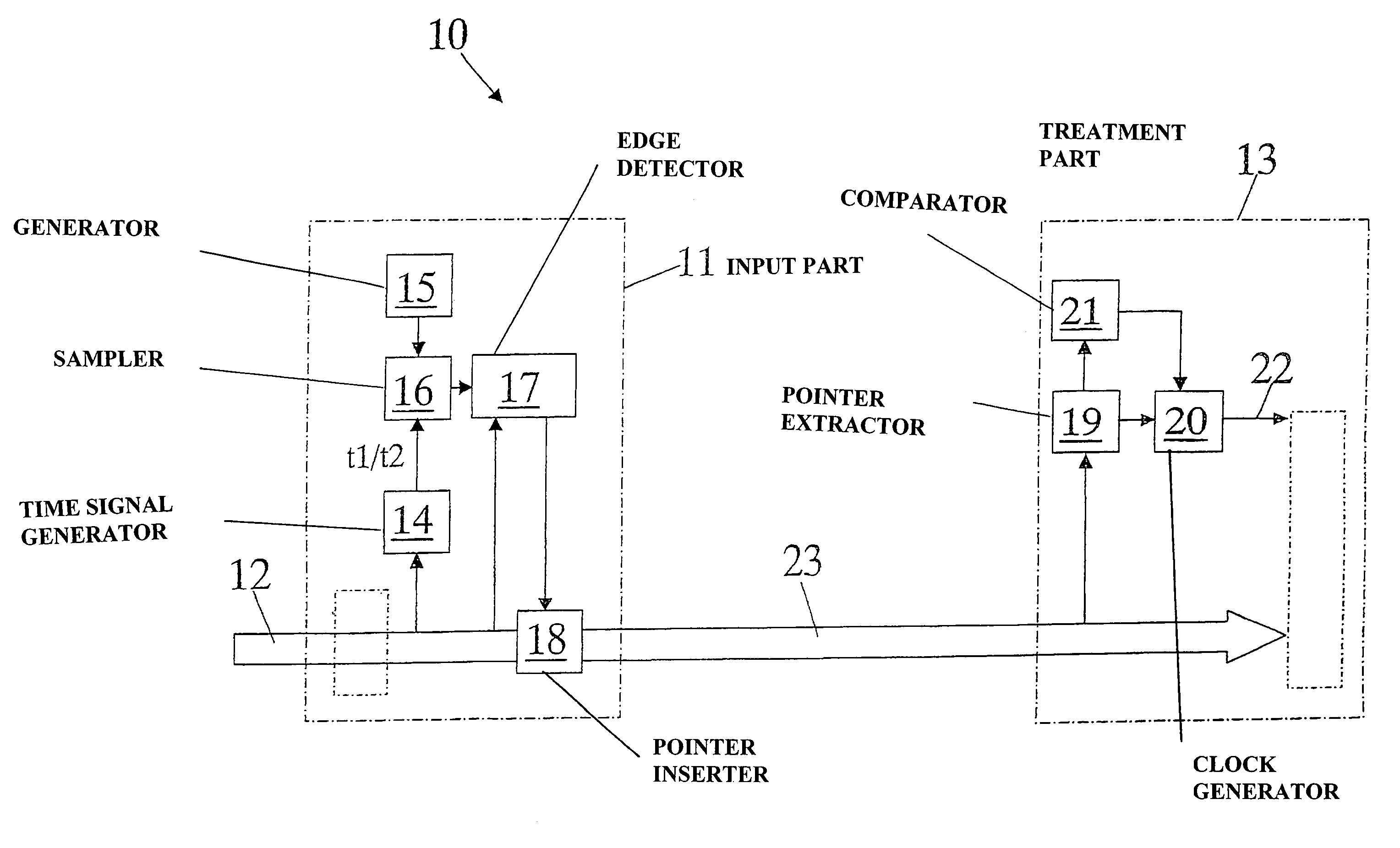
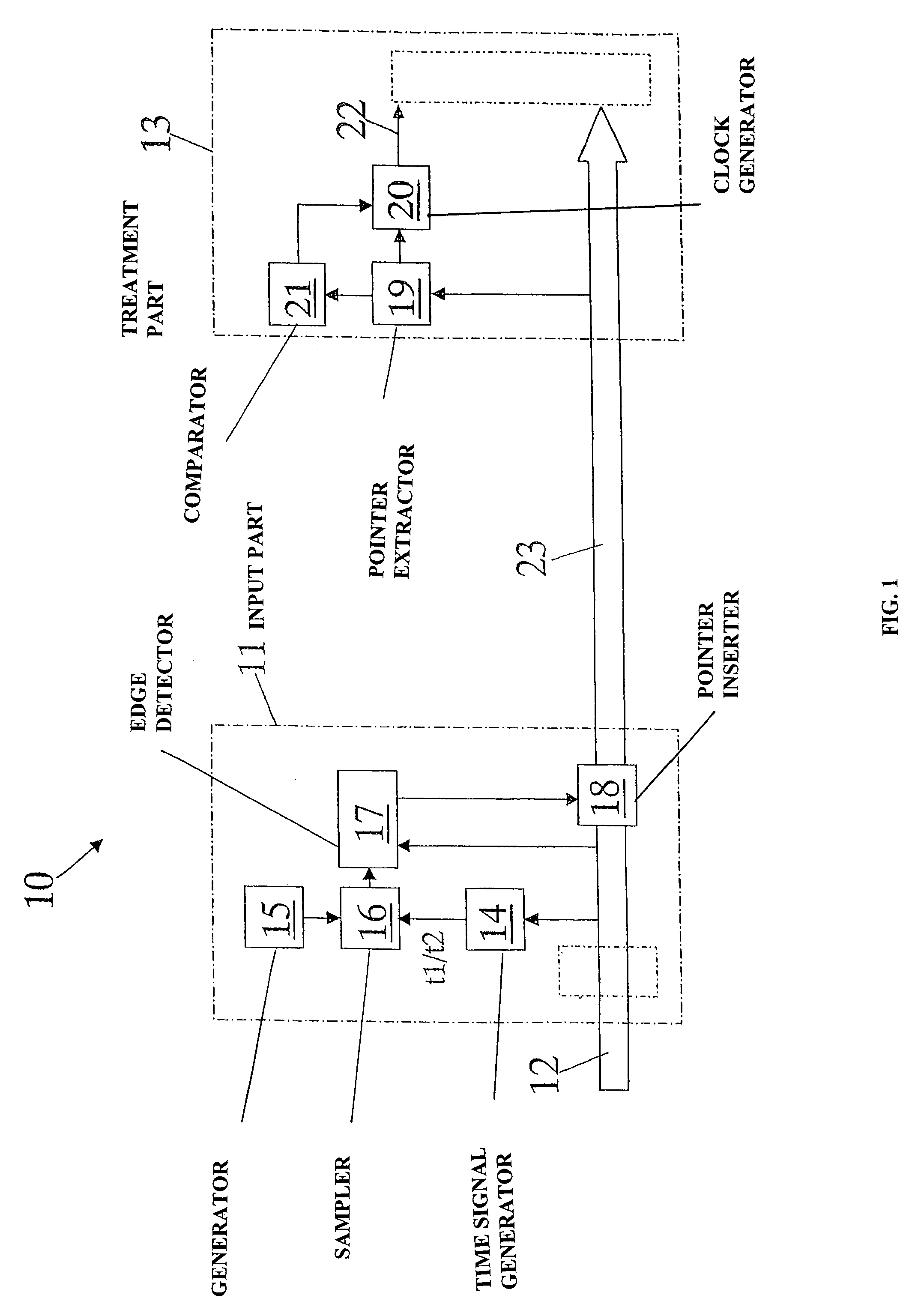
[0012]With reference to the figure an apparatus designated as a whole by reference number 10 of a telecommunications network is shown diagrammatically. This apparatus comprises an input part 11 receiving the input signals 12 and a part 13 for treatment of these input signals. The treatment part is the nucleus of the apparatus and can be very far from the input part. The input and treatment parts comprise the normal functions and devices of this type of equipment and they will therefore not be described in detail as they are readily imaginable to those skilled in the art.

[0013]As is known, the input part 11 and the treatment part 13 are interconnected by lines 23 for transport of the input signals with a frame structure.

[0014]The treatment part requires a clock synchronized with references derived from the input signals.

[0015]Basically, the idea is to use for synchronization the same cables 23 which transport the traffic data while encapsulating the synchronization data in the frames...


PUM


Abstract

A method for generation of a clock synchronized with time reference signals derived from input signals in an apparatus of a telecommunications network comprising an input part receiving the input signals and a treatment part for treatment of the input signals. In the input part the method comprises the steps of deriving the time reference signals from the input signals, reading an edge of the reference signals, establishing the position of this edge relative to the internal data frame, inserting in the frame heading a pointer representing the established position of the edge relative to the frame and sending the frame to the treatment part. In the treatment part the method comprises the steps of receiving the frame, extracting the pointer, generating the time reference clock and synchronizing it with the position in the frame indicated by the pointer. An apparatus applying this method is also proposed.

Description

BACKGROUND OF THE INVENTION[0001]The present invention relates to a method for the generation of timing signals in communication systems and networks and to an apparatus applying this method. The equipment inserted in a synchronous data transport network requires a function providing a timing source for correct operation. For example, the SETS function defined by ITU-T G.783 in the version of August 1997 represents the clock of the SDH network elements.[0002]The timing function includes an internal oscillator function supplying the system clock for all the equipment. The internal oscillator receives a reference clock supplied by a function which generates the timing for the synchronous equipment, for example SETG in SDH systems). The timing is chosen from among a series of possible synchronization sources derived from three possible reference points. These possible reference points are derived from the synchronous input signals, for example, STM-N, from the plesiochronous input sign...

Claims


Application Information

Patent Timeline
IPC IPC(8): H04B7/00H04J3/06H04L7/08
CPCH04J3/0691H04J3/0682
Inventor LANZONE, SERGIOTOSCANO, ORAZIO
Owner TELEFON AB LM ERICSSON (PUBL)
Why Eureka
Try Eureka