
System and method for applying an additive to a material stream

a technology of additives and material streams, applied in the field of feed processing systems, can solve the problems of uneven distribution of feed additives, adverse effects of feed on animals to which they are fed, and high concentration of additives,

Inactive Publication Date: 2008-10-28
SARTEC
View PDF35 Cites 12 Cited by
  • Summary
  • Abstract
  • Description
  • Claims
  • Application Information

AI Technical Summary

Benefits of technology

"The present invention is a system and method for adding liquid additives to a material stream. The system includes a mix housing and a spray housing, which are connected by a mix chamber. A nozzle is connected to the spray housing and creates a fog of liquid additive that is deposited on the material stream as it passes through the mix chamber. The material stream then passes through the mix chamber and is mixed with the liquid additive by an actuating device. The technical effect of this invention is that it allows for the efficient and effective mixing of liquid additives with material streams."

Problems solved by technology

Typically, these additives are metered and mixed into the feed through direct liquid injection by means of a micro ingredient machine or a liquid chemical pump, and then they are mixed in large chambers or containers, as a batch process; this process often leads to uneven distribution of the additive on the feed.
For example, a feed with an uneven distribution may have negative effects on the animals to which it is fed because some animals may get fed too much additive while others get fed too little additive.
The animals that ingest the feed with too high a concentration of additives may be harmed, or the excess additive may pass through the animal without achieving its desired effect.
Likewise, an animal that ingests feed with too little an additive content is not receiving the benefits intended by the additive.

Method used


Image

  • System and method for applying an additive to a material stream
  • System and method for applying an additive to a material stream
  • System and method for applying an additive to a material stream

Examples


Embodiment Construction

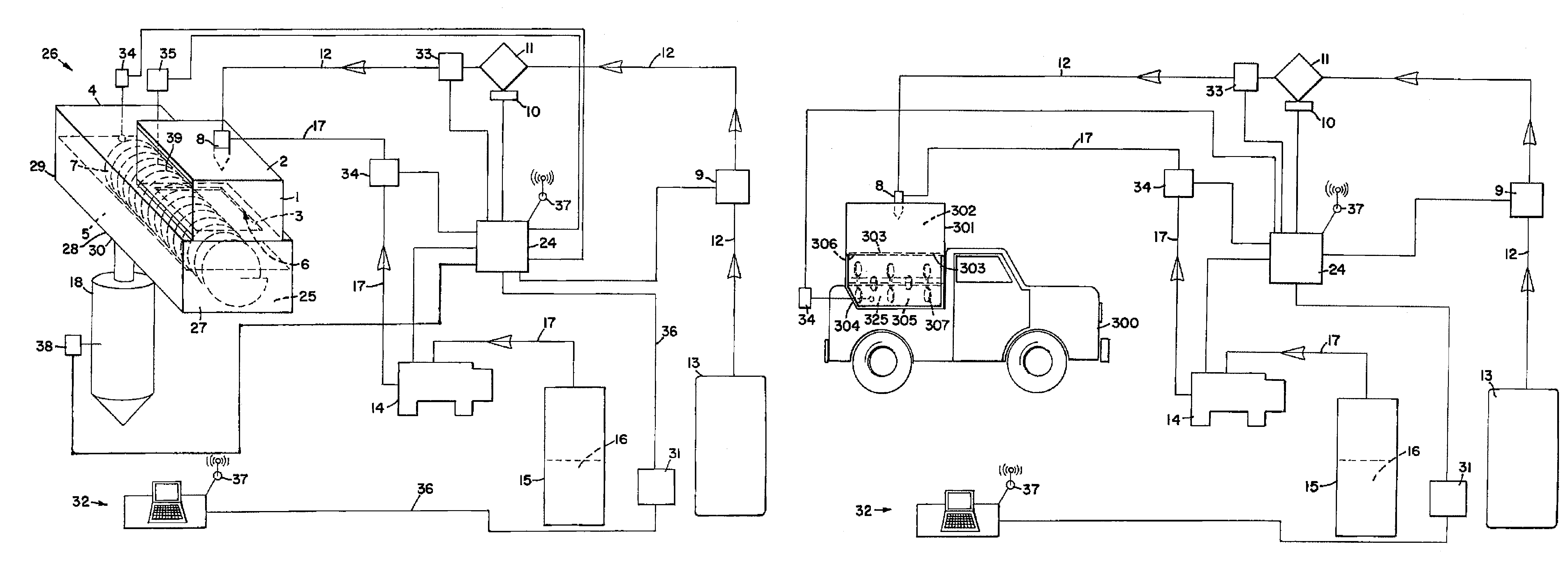
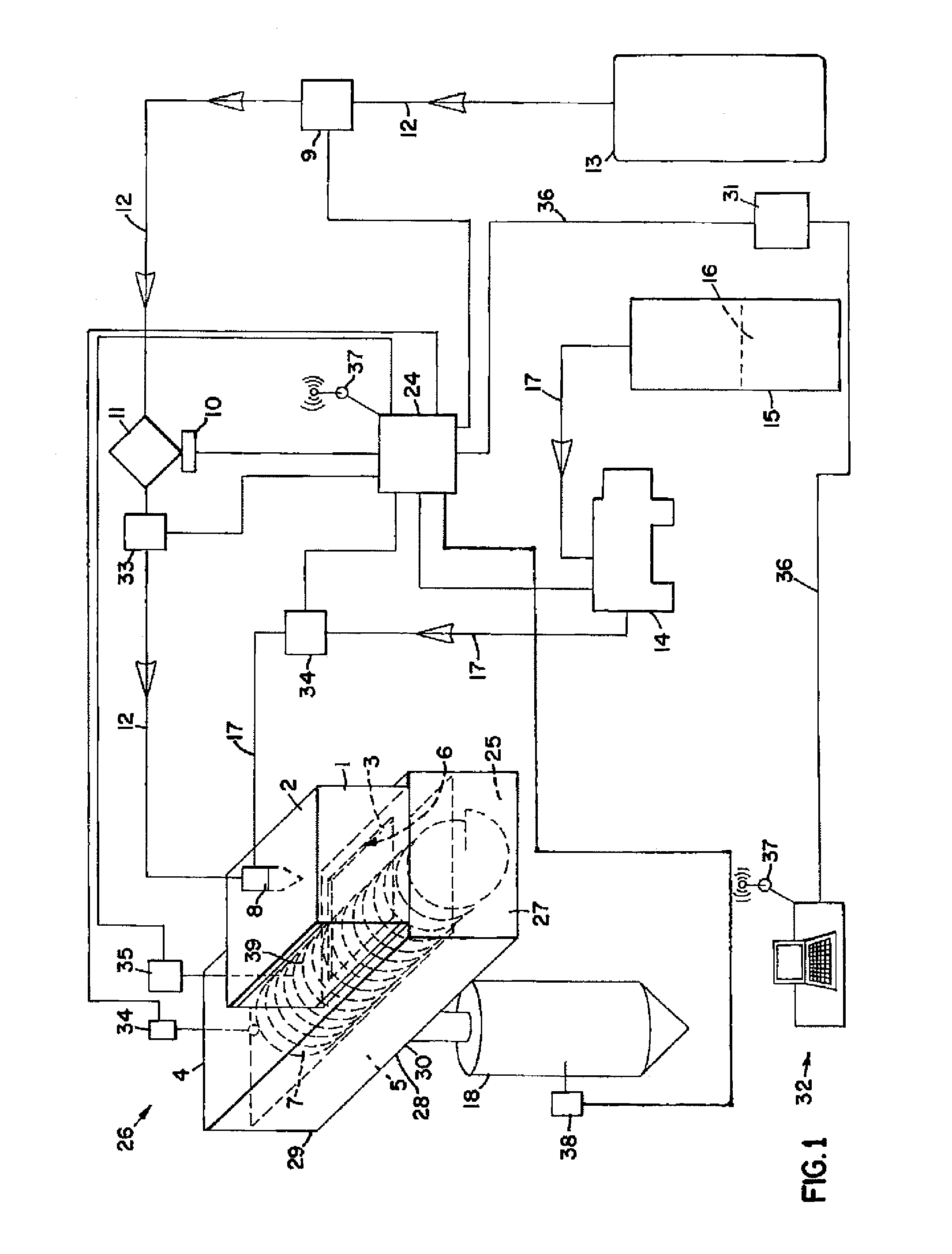
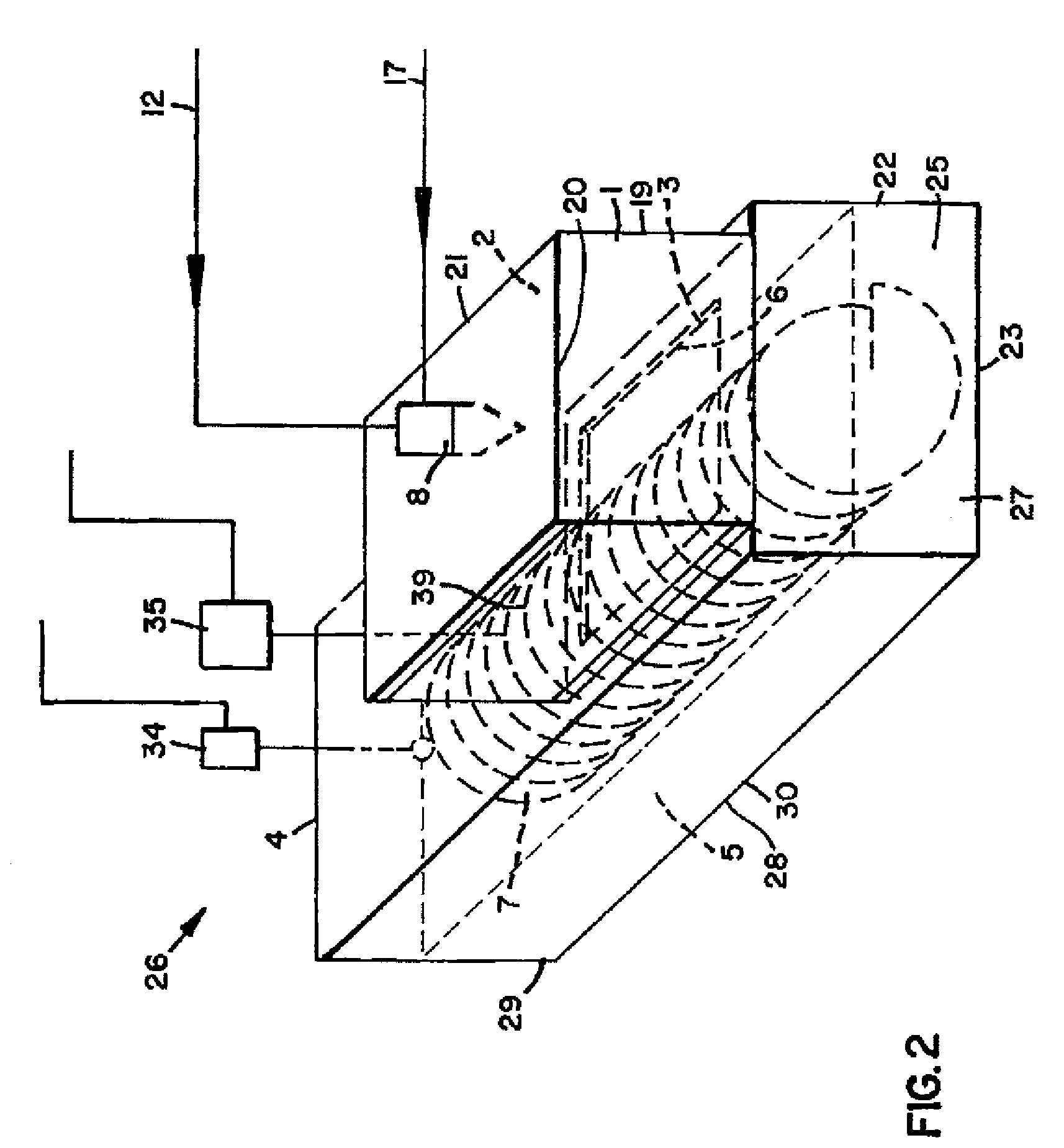
[0012]Referring now to the drawings in which similar elements are numbered identically throughout, descriptions of embodiments constructed according to the principles of the present disclosure are provided. Referring now to FIGS. 1 and 2, the system 26 generally includes, among other elements described below, an air source 13, an additive tank 15, an additive pump 14, additive line 17 and air line 12, a spray nozzle 8, a spray housing 1, a mix housing 4, an actuating device 7 and a control unit 24.

[0013]FIGS. 1 and 2 illustrate one embodiment of a mix housing 4 made according to the principles of the present disclosure. The mix housing 4 defines a mix chamber 5 and a mix chamber opening 6. The mix housing 4 is used to transport material from one point in a feed processing plant to another point in the feed processing plant. Inside the mix chamber 5 is an actuating device 7. While inside the mix housing 4, the material stream 25 is progressed through the mix chamber 5 and mixed by th...


PUM

PropertyMeasurementUnit
temperatureaaaaaaaaaa
diameteraaaaaaaaaa
widthaaaaaaaaaa

Abstract

The present disclosure is generally directed to systems and methods for applying liquid feed additives to a feed composition. In one embodiment, the system has a spray housing defining a spray chamber located adjacent a mix housing carrying a material composition. The mix housing defines a mix chamber, which contains an actuating device, such as an auger, that moves the material stream through the mix chamber. The mix chamber and spray chamber are in fluid communication. A spray nozzle is coupled to the spray housing and in fluid communication with an air source and liquid additive tank. The spray nozzle sprays a fog of air and liquid additive through the spray chamber and into the mix chamber, which gets deposited on the passing feed stream.

Description

[0001]This is a continuation application of co-pending application Ser. No. 10 / 440,432, filed on May 16, 2003, which application is hereby incorporated by reference in its entirety.FIELD OF THE INVENTION[0002]This invention relates generally to the field of feed processing systems and more particularly to systems and methods for combining additives with feed.BACKGROUND OF THE INVENTION[0003]Many livestock producers use processed feed to raise livestock, such as poultry, cattle, swine, sheep and dairy and beef cattle, rather than unprocessed feed or allowing the animals to graze on open pastures. Processed feed allows producers to achieve greater production in less space and at lower operating costs. In addition to the advantage of raising a larger number of animals on less land, processed feed allows producers to tailor the feed's nutrition qualities for specific types of animals. Thus, not only can more animals be produced on less land, processed feed also enables the animals to gr...

Claims


Application Information

Patent Timeline
Patent Type & Authority Patents(United States)
IPC IPC(8): B01F15/02B05B17/00A01K5/00B01F3/12B01F7/02B01F7/04B01F7/08B01F7/18B01F13/00
CPCB01F3/1221B01F3/1228B01F7/022B01F7/04B01F7/086B01F7/18B01F13/0035B01J2/10B01F2215/0008B01F2215/0014Y10S119/902B01F23/54B01F23/53B01F27/62B01F27/724B01F27/70B01F27/90B01F33/502B01F2101/18B01F2101/06
Inventor MCNEFF, LARRY C.MCNEFF, CLAYTON V.JOHNSTON, DAVID J.GREUEL, PETER G.
Owner SARTEC
Learn More