Tidal turbine installation

a technology of tidal turbines and installation platforms, which is applied in the direction of motors, sea energy generation, tidal stream/damless hydropower, etc., can solve the problems of serious threat to the apparatus, and achieve the effects of increasing the flow speed, high flow speed, and stabilizing the apparatus

Active Publication Date: 2008-10-28
AQUA LIBRE ENERGIEENTWICKLUNGS
View PDF17 Cites 22 Cited by
  • Summary
  • Abstract
  • Description
  • Claims
  • Application Information

AI Technical Summary

Benefits of technology

[0009]The relevant aspect in the present invention is the fact that in normal operations the turbine is located at optimal level directly beneath the water surface. This optimal level is set by flooding or venting the floating bodies, i.e. the cavities. When the water level is low, the apparatus is held by the anchor cable at the location intended for the same and the rise-limiting cable is loose. When the water level rises, the apparatus rises accordingly with the water level until the rise-limiting cable is tightened at high normal water level. If the water level continues to rise, any further rise of the apparatus is prevented by the now perpendicularly stretched rise-limiting cable. Especially at high water there is a clearly increased likelihood that flotsam such as trees that have been torn away are transported on the water surface. In conjunction with the clearly increased flow speed at high water, this would pose a serious threat to the apparatus if the same were situated directly beneath the water surface. As a result of the rise-limiting means however it is possible to prevent such damage in all probability. It is of special advantage in this connection that as a result of the generally increased flow speed in the case of high water no power losses need to be feared because sufficiently high flow speeds for efficient power generation are available in this case too beneath the water surface. It is optimal in this connection when the rise-limiting cable leads perpendicularly downwards in the used position of the apparatus and is anchored in the ground of the river and / or is loaded by a weight, and that the rise-limiting cable preferably has a length which corresponds to the normal water level of the river.
[0010]In order to stabilize the apparatus in the lateral direction as well, it is especially advantageous when two anchor cables are provided which are fastened to the bow of the housing at the same level. An especially simple configuration which offers a possibility for modular expansion can be achieved in such a way that the inside housing comprises a substantially square inlet cross section, a turbine pipe cylinder which is arranged downstream of the same and an adjacent expanding outlet with a rectangular cross section. Increased stability in the flowing river is thus also achieved in this way. As a result of the outlet situated downstream, a diffuser-like effect occurs which increases the efficiency. In this connection it is of further advantage when the outside housing comprises a continuous rectangular cross section which preferably expands towards the downstream side. This measure too is used for stability and efficiency.
[0011]An optimal adjustment and alignment of the apparatus in accordance with the invention can be achieved in such a way that the cavities are subdivided in the longitudinal direction and can be filled with water and / or compressed air. This enables a simplified maintenance of the apparatus in particular.
[0012]An especially preferred embodiment of the present invention provides an inlet rake at the bow of the housing, which rake consists of a floating body which stands perpendicularly in the used position and extends over the entire height of the housing, and from which extend profiles or cables which are arranged in a V-shaped manner and are fastened to the lateral inlet edges of the housing. It has been seen that such a configuration allows for an outstanding stability of the apparatus, especially about the transversal axis, and simultaneously deflects small and medium-sized flotsam floating against the apparatus without damaging the apparatus. Such flotsam will usually meet the perpendicular floating body which is provided with a respectively robust configuration. The floating body will displace the flotsam to the right or left, which will then slide off the V-shaped arranged profiles on the apparatus. It is of special advantage in this connection that the flotsam will usually not exert any perpendicular forces or moments on the apparatus because they are more difficult to compensate than horizontal forces or moments.
[0013]Increased stability can be achieved by additional floating bodies on the upper side of the outside housing.
[0014]In order to avoid any damage to the apparatus during extreme low water it is advantageous when spacer feet are provided on the bottom side of the outside housing. They will ensure under all circumstances a sufficient distance from the ground of the river.

Problems solved by technology

In conjunction with the clearly increased flow speed at high water, this would pose a serious threat to the apparatus if the same were situated directly beneath the water surface.

Method used


Image

  • Tidal turbine installation
  • Tidal turbine installation

Examples


Embodiment Construction

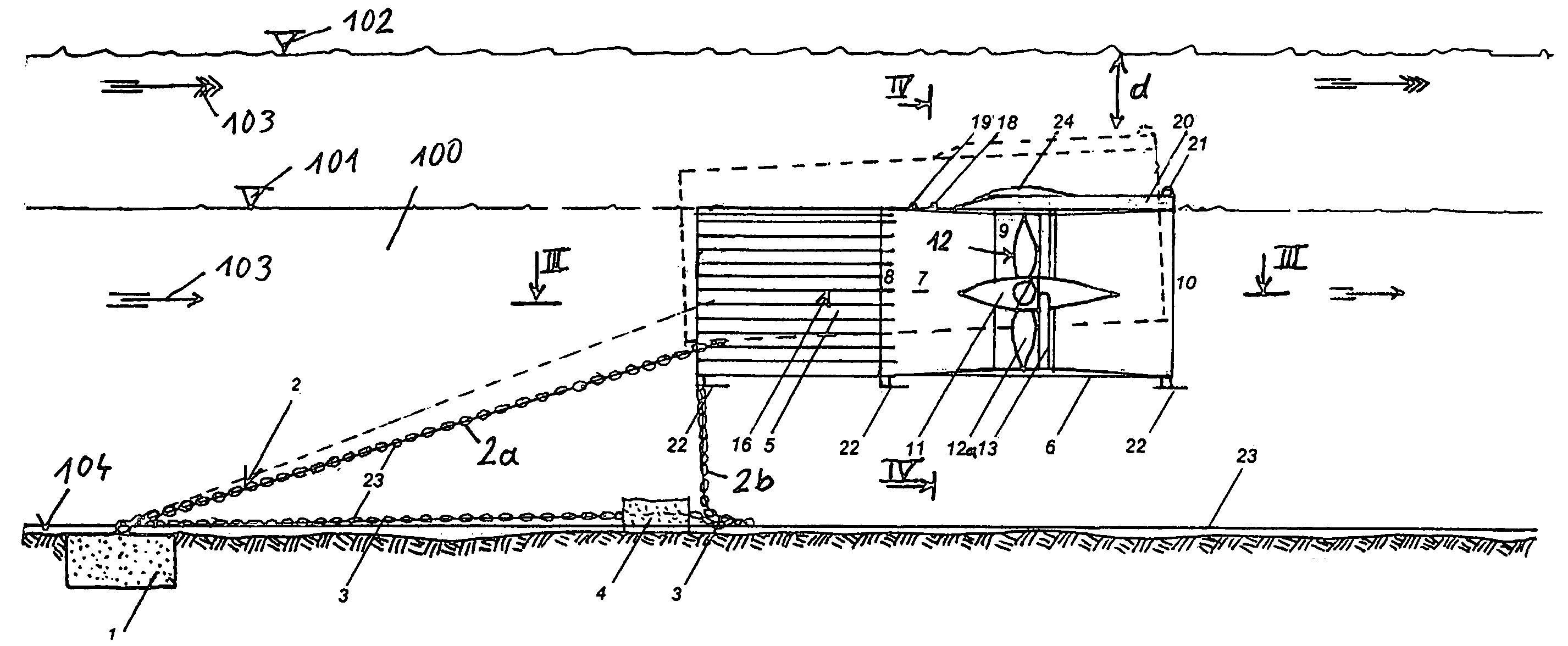
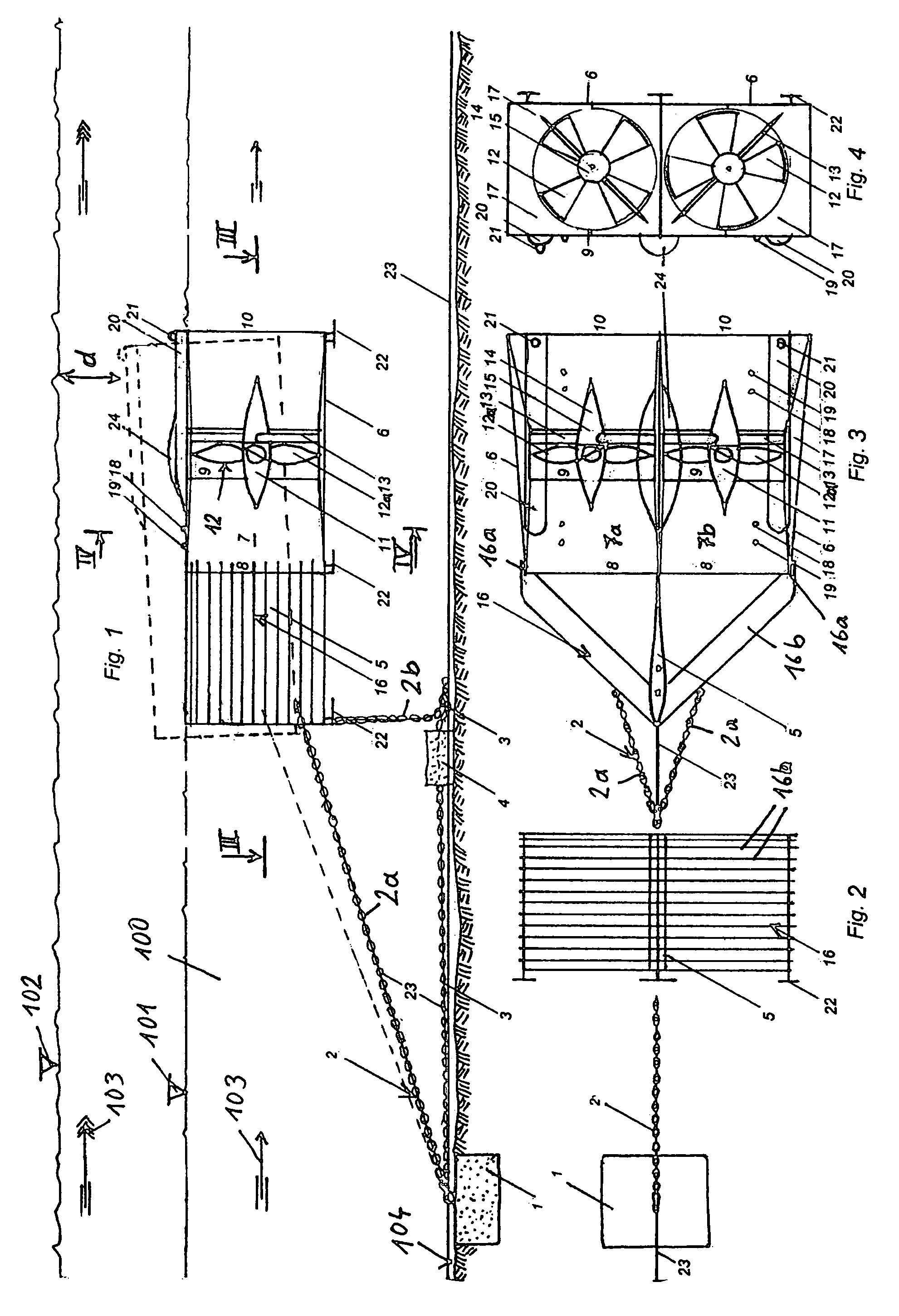
[0020]FIG. 1 shows a river 100 in which the apparatus in accordance with the invention is installed. The water level is labeled with reference numeral 101 at normal water level, whereas the water level at high water is labeled with 102. The direction of flow is indicated by arrows 103.

[0021]A heavy anchor 1 is inserted into the ground 104 of the river 100, to which the traction means is fastened which is generally designated with reference numeral 2 and which holds the apparatus at the place intended for its purpose. The traction means 2 consists in detail of two anchor cables 2a and a rise-limiting cable 2b. The rise-limiting cable 2b is held by a weight 4 on the ground 104 of the river and is used to limit the rising level of the apparatus. In order to simplify the anchoring, the rise-limiting cable 2b is guided by weight 4 further to the anchor 1 and is also anchored there.

[0022]In the position of the apparatus which is shown in FIG. 1 with the unbroken line, the level of the app...


PUM


Abstract

An apparatus for generating electric power in freely flowing rivers includes a housing formed of an outside housing (6) and an inside housing (7) having an outlet (10) formed as a suction pipe, with cavities (17) being provided between the outside housing (6) and the inside housing (7) in order to stabilize the apparatus close beneath the water surface, and with at least one turbine (12) arranged in the inside housing (7) which is flowed through axially and is connected with a generator (14), and with a traction means (2) for anchoring the apparatus. A robust apparatus which is especially protected against hazards caused by high water can be achieved in such a way that the traction means (2) is provided by at least one longer anchor cable (2a), with the anchor cable (2a) being anchored in the used position in an inclined manner in front of the apparatus in the ground of the river, and of at least one shorter rise-limiting cable (2b).

Description

CROSS-REFERENCE TO RELATED APPLICATION[0001]This is a continuation-in-part of International Application PCT / AT2005 / 000025, filed 28 Jan. 2005, which designated the U.S. All priorities are claimed.BACKGROUND OF THE INVENTIONFIELD OF THE INVENTION[0002]The invention relates to an apparatus for generating electric power in freely flowing rivers, comprising a housing consisting of an outside housing and an inside housing having an outlet formed as a suction pipe, with cavities being provided between the outside housing and the inside housing in order to stabilize the apparatus close beneath the water surface, and with at least one turbine arranged in the inside housing which is flowed through axially and is connected with a generator, and with a traction means for anchoring the apparatus.[0003]So-called power buoys are known which are suspended in freely flowing rivers in order to generate electric power from the energy of flow of the river. The advantage of such power buoys is that the...

Claims


Application Information

Patent Timeline
Patent Type & Authority Patents(United States)
IPC IPC(8): F03D11/04F04D29/60F03B13/26F03B17/06
CPCF03B13/26F05B2240/40Y02E10/38Y02E10/28F05B2240/97Y02E10/30Y02E10/20
Inventor MONDL, FRITZ
Owner AQUA LIBRE ENERGIEENTWICKLUNGS
Why Eureka
Try Eureka