Fuel-conditioning skid

a technology of fuel-conditioning skid and skid body, which is applied in the direction of combustion-air/fuel-air treatment, cartridge filters, combination devices, etc., can solve the problems of fuel system and/or engine problems, and achieve the effect of reducing the possibility of condensing liquid

Inactive Publication Date: 2008-10-28
FLEXENERGY ENERGY SYST
View PDF16 Cites 109 Cited by
  • Summary
  • Abstract
  • Description
  • Claims
  • Application Information

AI Technical Summary

Benefits of technology

[0006]In still another aspect, the invention generally provides a method of conditioning a flow of fuel to make the flow of fuel suitable for combustion within an engine. The method includes delivering the flow of fuel to a fuel-conditioning skid, the flow of fuel including undesirable compounds. The method also includes filtering the flow of fuel to remove at least a portion of the undesirable compounds from the flow of fuel and compressing the flow of fuel. The method further includes cooling the flow of fuel in a plurality of cooling stages to condense at least a portion of the undesirable compounds and draining the condensed undesirable compounds from the flow of fuel during each of the plurality of cooling stages. The fuel flow is then reheated to raise the fuel temperature above its dew point to minimize the possibility of condensing liquids between the fuel conditioning skid and the engine. The method also includes directing the flow of fuel to the engine.

Problems solved by technology

The fuels from the above-mentioned sources contain constituents and contaminants that can cause problems in the fuel system, and / or the engine.

Method used


Image

  • Fuel-conditioning skid
  • Fuel-conditioning skid
  • Fuel-conditioning skid

Examples


Embodiment Construction

[0015]Microturbine engines are relatively small and efficient sources of power. Microturbines can be used to generate electricity and / or to power auxiliary equipment such as pumps or compressors. When used to generate electricity, microturbines can be used independent of the utility grid or synchronized to the utility grid. In general, microturbine engines are limited to applications requiring 2 megawatts (MW) of power or less. However, some applications larger than 2 MW may utilize one or more microturbine engines.

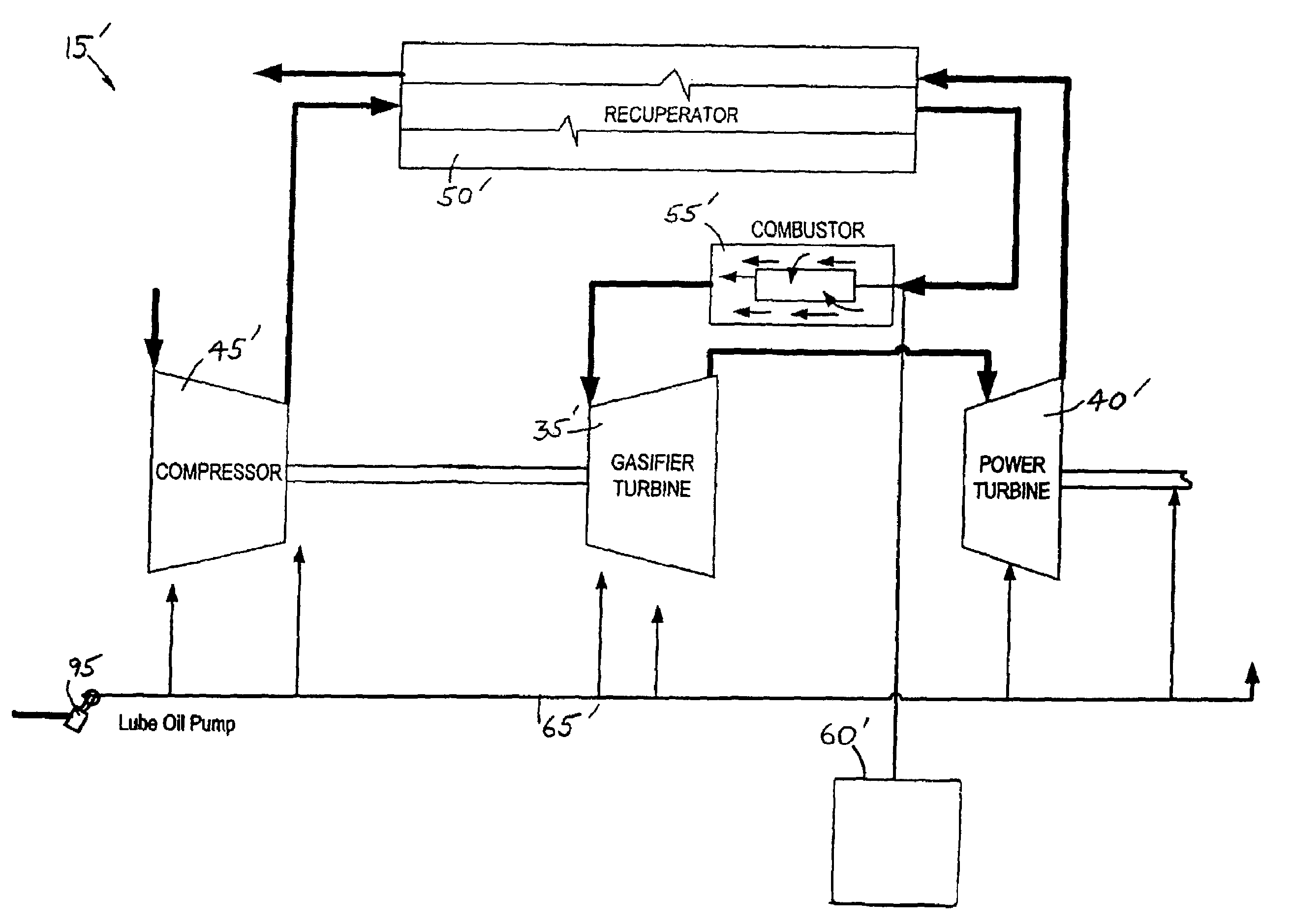
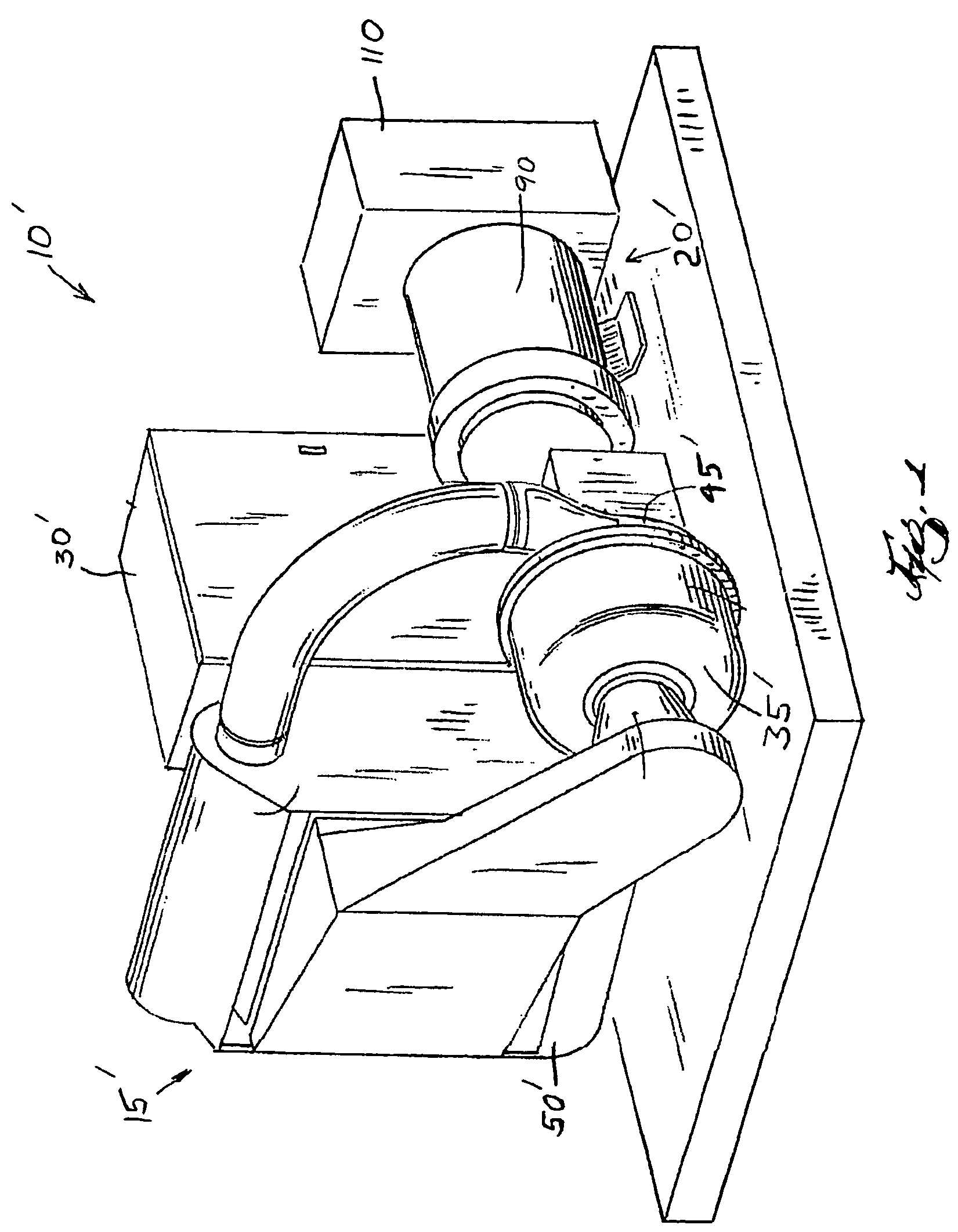
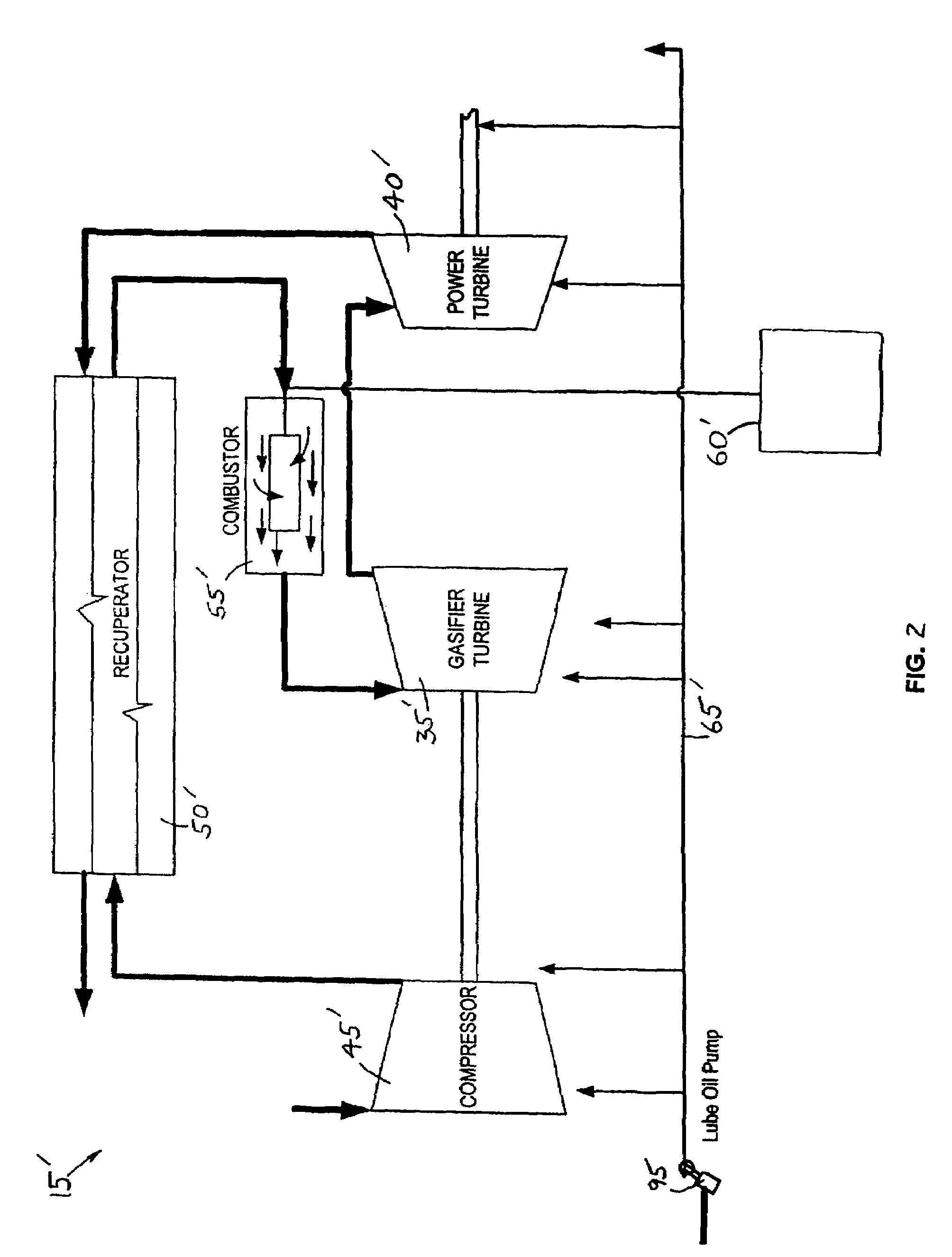
[0016]With reference to FIGS. 1 and 2, the microturbine engine system 10′ includes a turbine section 15′, a generator section 20′, switch gear (not shown), and a control system 30′.

[0017]The turbine section 15′, schematically illustrated in FIG. 2, includes a gasifier turbine 35′, a power turbine 40′, a compressor 45′, a recuperator 50′, and a combustor 55′. The turbine section 15′ also includes various auxiliary systems such as a fuel supply system or fuel skid 60′ and a...


PUM

PropertyMeasurementUnit
pressureaaaaaaaaaa
poweraaaaaaaaaa
sizeaaaaaaaaaa

Abstract

A fuel-conditioning skid for an engine. The fuel-conditioning skid includes an inlet that is connectable to a source to receive a flow of fuel containing undesirable compounds. An outlet is connectable to the engine to deliver a flow of fuel that is substantially free of undesirable compounds. An inlet cleaner is in fluid communication with the inlet and is operable to remove a portion of the undesirable compounds. A compressor is in fluid communication with the inlet cleaner to receive the flow of fuel at a first pressure and discharge the flow of fuel at a second pressure. The second pressure is greater than the first pressure. A purifier is in fluid communication with the inlet cleaner to receive the flow of fuel. The purifier is operable to remove substantially all of the remaining undesirable compounds from the flow of fuel.

Description

RELATED APPLICATION DATA[0001]This application claims benefit under 35 U.S.C. Section 119(e) of U.S. Provisional Patent Application Ser. No. 60 / 457,072, filed Mar. 24, 2003.BACKGROUND OF THE INVENTION[0002]Hydrocarbon-based fuels are available from a variety of sources including biogas from landfills, wastewater treatment plants, agricultural and other digesters, light hydrocarbon gases from oil and gas wells, and various heavier hydrocarbon gases from processes such as refinery processing. These fuels can be used in an engine to generate electricity and heat. These fuels can be combusted either in a gas turbine engine (Brayton cycle), an internal combustion engine (Otto cycle), or other prime-mover engines (e.g., Sterling engines). Any of these engines can be connected to an electric generator to generate electricity or a shaft to provide shaft power for a variety of applications. The electric generator would produce electricity, which could either be exported to the electric utili...

Claims


Application Information

Patent Timeline
Patent Type & Authority Patents(United States)
IPC IPC(8): B01D19/00F02C3/10F02C3/22F02M21/02F02M31/16F02M37/22F23D14/68F23K5/00F23K5/18F23R3/30
CPCF02C3/10F02C3/22F02M31/16F02M37/22F23D14/68F23K5/007F23K5/18F23R3/30F02M21/0215F02M21/0227F02M21/0287F23C2900/03001F23K2401/10Y02E20/14Y02T10/126Y02T10/32F02D19/022F02M37/40F02M37/42F02M37/54F23K2400/10Y02T10/12Y02T10/30
Inventor ARMSTRONG, JEFFREY A.SULLIVAN, SHAUNROSLUND, ERIC
Owner FLEXENERGY ENERGY SYST
Why Eureka
Try Eureka