Clamping device

a technology of a clamping device and a clamping plate, which is applied in the direction of slendering auxillary devices, manual control with multiple controlling members, manual control with single controlled members, etc., can solve the problems of deformation of components, clamping problems, and some clamping tasks, and achieve the effect of improving the clamping techniqu

Inactive Publication Date: 2008-10-28
KUKA SYSTEMS
View PDF13 Cites 3 Cited by
  • Summary
  • Abstract
  • Description
  • Claims
  • Application Information

AI Technical Summary

Benefits of technology

[0007]The clamping device or system being claimed has the advantage that it leads to better clamping results, has a smaller space requirement and can be designed, in particular, as a very flat clamping device or system. Moreover, the clamping device or system has considerably more free space for machining devices. Special advantages arise when entire cutouts or contours are to be clamped all at once on components, which happens, e.g., in case of body openings, connection sites between body parts, e.g., the side wall and the roof part or the like.
[0008]The clamping devices being claimed make it possible to create any desired geometry with a minimum space requirement with the clamping segments. Due to the flat design, it is possible now to keep the clamping units closed during the machining of the flange, e.g., during laser seam welding and to create and maintain defined clamping and process conditions as a result. Furthermore, it is possible to actuate the clamping units together in a controllable sequence and to feed them preferably simultaneously in the process and to bring them into a clamped connection. As a result, exactly defined clamping conditions can be created, and undesired deformations of the components are avoided.
[0009]Special advantages arise when internal flanges at openings of components, especially door or window openings of body components, are to be clamped. The component flange can be clamped circumferentially with a simple clamping device, it can be fed to the component opening thanks to the preferred feed and clamping kinematics of the clamping device with retracted movable clamping units. The retracted clamping units can now be moved past the flange of the component and then fed to the rear side of the flange and brought into the clamped position. As an alternative, clamping of one or more component flanges located on the outside is possible.

Problems solved by technology

Due to their size, the individual clamping units can be arranged at greater distances only, which leads to problems for some clamping tasks.
On the other hand, deformations of the components may occur because the individual clamping units are usually closed offset in time and due to the punctiform clamping action.
This may likewise lead locally to clamping problems because of the great distances between the clamping units, especially when the flange of the component is opened and undesired or excessively large gaps are formed as a result between the components.
Special problems arise during the clamping of component flanges at openings in the body, e.g., door or window openings.
The individual clamping units often fail to satisfactorily accomplish the clamping tasks for the above-mentioned reasons.
In addition, they hinder access for machining devices, e.g., welding robots, etc., due to their large space requirement.
On the whole, the clamping means equipped with individual clamping units inherently have the drawbacks of having a large space requirement and a heavy weight, requiring great efforts for assembly and adjustment and a correspondingly high price.

Method used


Image

  • Clamping device
  • Clamping device
  • Clamping device

Examples


Embodiment Construction

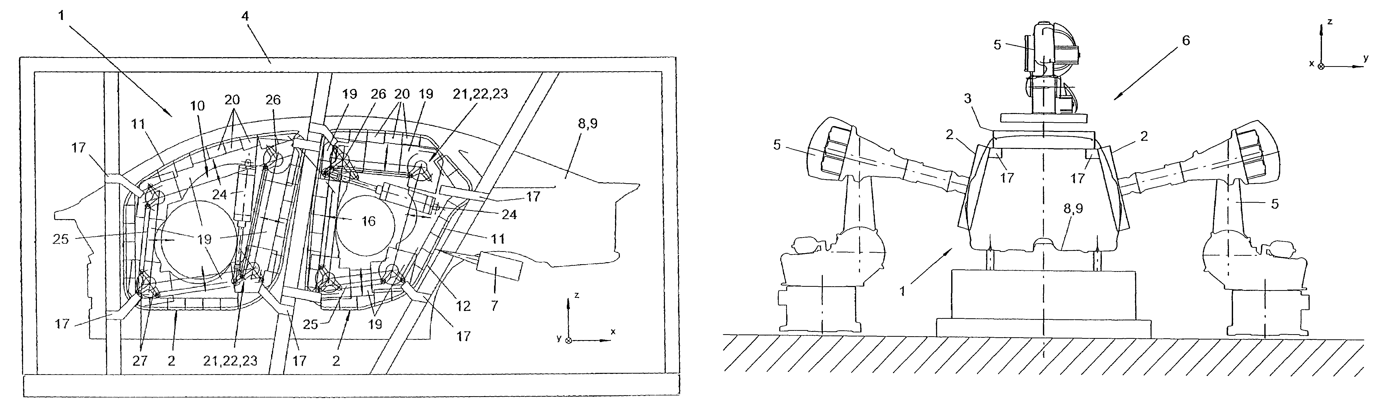
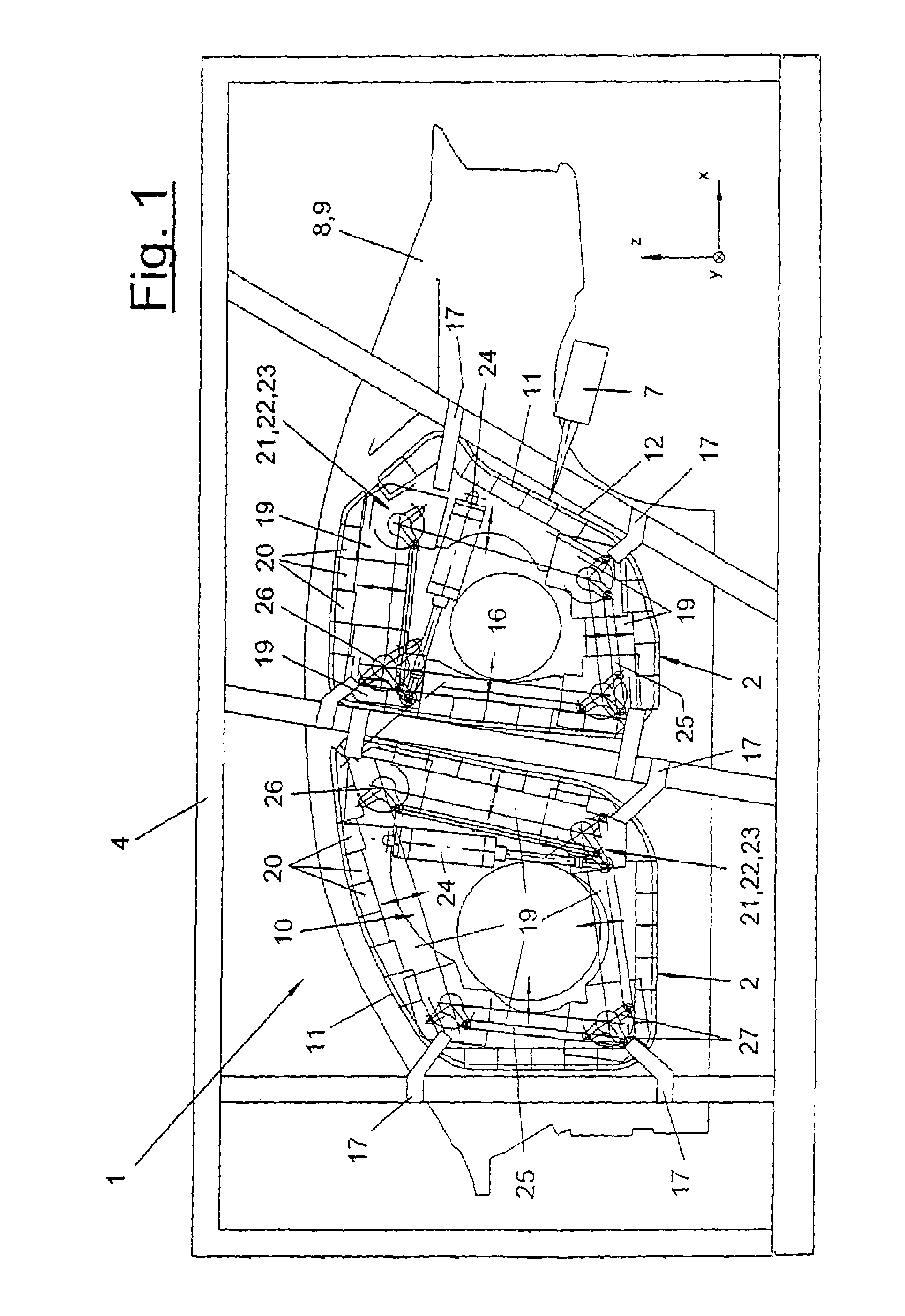
[0036]Referring to the drawings in particular, the present invention pertains to a clamping device or system 1, which comprises at least one or more clamping devices 2, 3, which will hereinafter be described in detail. Furthermore, one or more feed devices, which are designed as a clamping frame 4 in one variant and as a robot 5 in the other variant in the exemplary embodiments being shown, belong to the clamping device or system 1. The present invention pertains, in addition, to a machining station 6, especially a framing station or geo station, with such a clamping device or system 1 and additional components, not shown, e.g., machining devices, especially welding robots, tool magazines, component conveyors and the like.

[0037]The clamping device or system 1 is used to clamp components 8, 9. These are preferably body parts. However, the components 8, 9 may otherwise be any other desired workpieces. The components 8, 9 clamped together may be machined or treated in any desired manne...


PUM

PropertyMeasurementUnit
anglesaaaaaaaaaa
heightaaaaaaaaaa
pressureaaaaaaaaaa

Abstract

A clamping device or system (1) is provided for body parts (8, 9), which have a component clamping contour (11), especially a component flange. The clamping device or system (1) has one or more clamping devices (2, 3), which have each a frame-like structure (12) with fixed and mobile clamping units (18, 19) arranged therein, which are present in a plurality of pairs. The clamping units (18, 19) have a strip-shaped design and are adapted to the course of the component clamping contour. Furthermore, the clamping device or system (1) has an adjusting device (21), which feeds the mobile clamping units (19) to the component clamping contour and actuates them together or in a controllable sequence.

Description

CROSS REFERENCE TO RELATED APPLICATIONS[0001]This application is a United States National Phase application of International Application PCT / EP2004 / 007754 of Jul. 14, 2004 and claims the benefit of priority under 35 U.S.C. § 119 of German Application DE 203 12 401.4 filed Aug. 6, 2002, the entire contents of which are incorporated herein by reference.FIELD OF THE INVENTION[0002]The present invention pertains to a clamping device or system for components, especially body parts.BACKGROUND OF THE INVENTION[0003]It is known and common in the practice of manufacturing vehicle body shells to clamp the body parts by means of clamping frames in so-called framing stations or even in downstream welding stations. These clamping frames comprise a massive frame, on which a plurality of individual clamping units are arranged at the needed locations. A plurality of components can be clamped together with these individual clamping units, and a component flange that is needed for the welded connecti...

Claims


Application Information

Patent Timeline
Patent Type & Authority Patents(United States)
IPC IPC(8): B23K37/04B62D65/02B62D65/06
CPCB23K37/0435B62D65/06B62D65/02Y10T74/20305
Inventor STURM, THOMAS
Owner KUKA SYSTEMS
Why Eureka
Try Eureka