Level shifting circuit

a level shifting circuit and level shifting technology, applied in logic circuits, pulse automatic control, pulse technique, etc., can solve problems such as extra circuitry and substantial current leakag

Inactive Publication Date: 2008-10-28
NXP USA INC
View PDF10 Cites 49 Cited by
  • Summary
  • Abstract
  • Description
  • Claims
  • Application Information

AI Technical Summary

Problems solved by technology

Some level shifters require extra circuitry and / or they may be a source of substantial current leakage, especially if they lack the extra circuitry.

Method used


Image

  • Level shifting circuit
  • Level shifting circuit
  • Level shifting circuit

Examples


Embodiment Construction

[0014]The following sets forth a detailed description of a mode for carrying out the invention. The description is intended to be illustrative of the invention and should not be taken to be limiting.

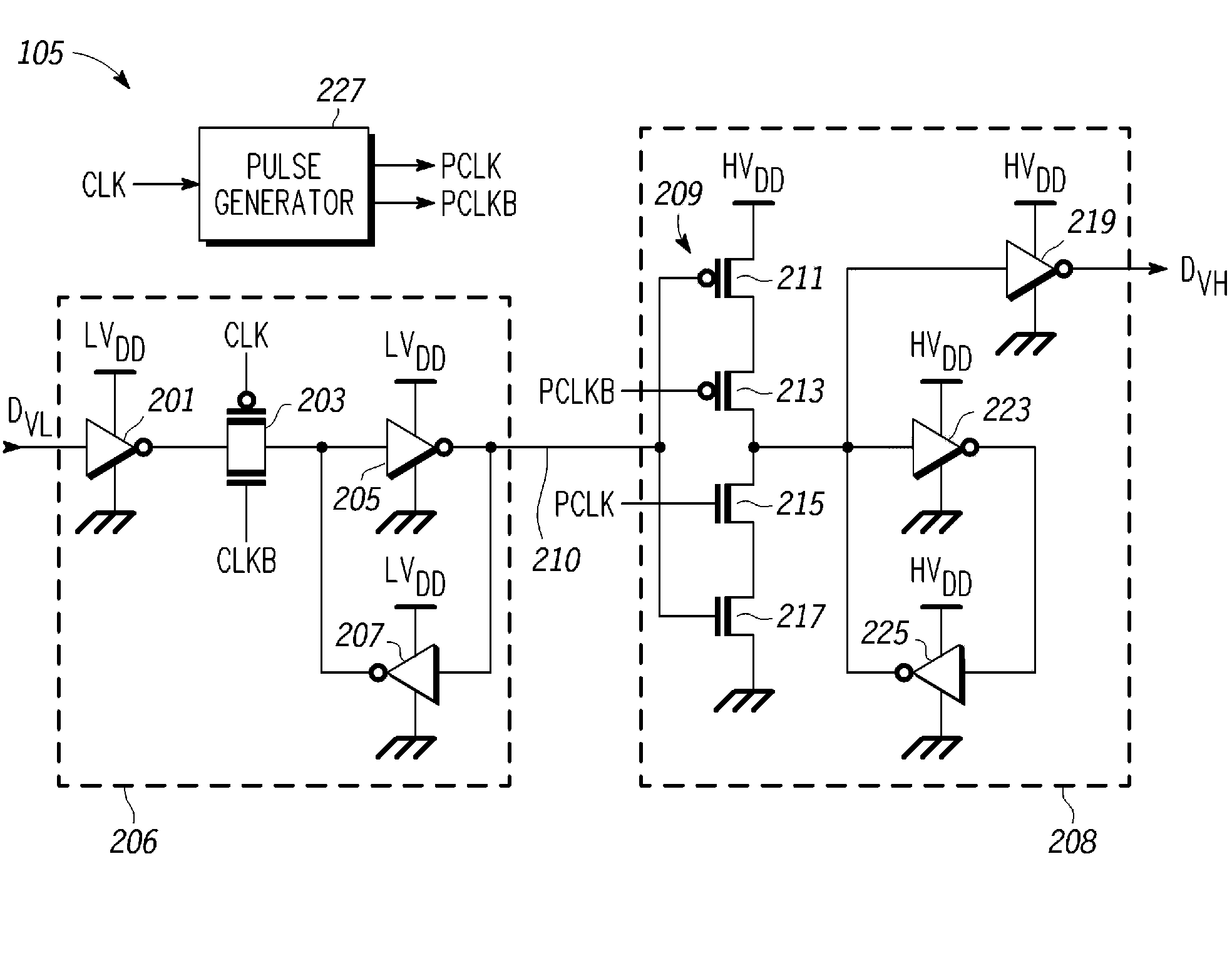
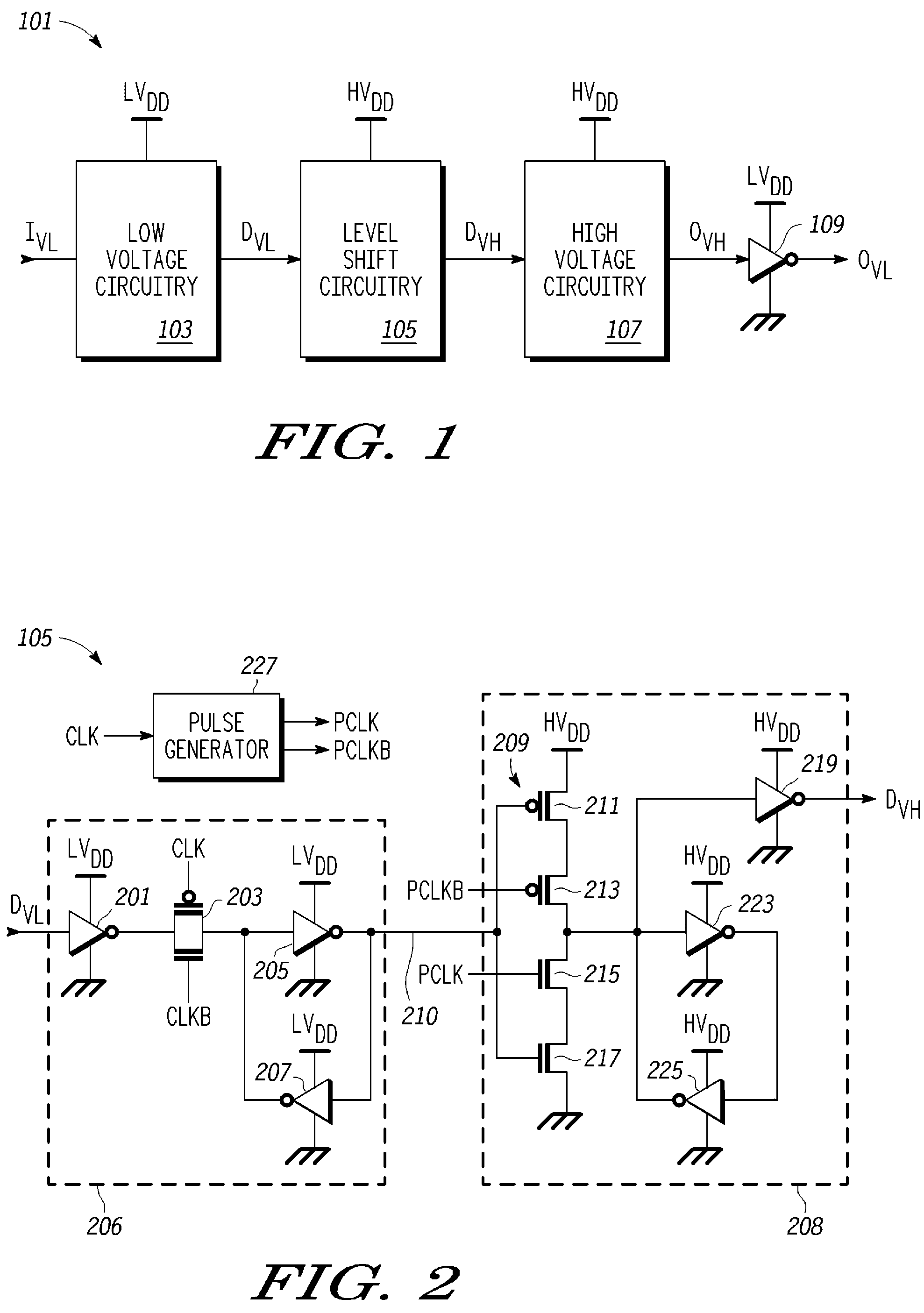
[0015]FIG. 1 is a block diagram of a circuit with a level shifting circuit according to one embodiment of the present invention. Circuit 101 includes low voltage circuitry 103 and high voltage circuitry 107. Low voltage circuitry 103 operates in a low voltage domain wherein the circuitry is powered by a low voltage power supply (LVDD), and high voltage circuitry 107 operates in a high voltage domain wherein the circuit is powered by a high voltage (HVDD) power supply. The designation of “high voltage” and “low voltage” with respect to this embodiment is used to differentiate the power supplies by voltage level relative to each other.

[0016]In one embodiment, circuit 101 is a part of a memory system wherein the high voltage circuitry 107 includes a memory array (not shown) and associated c...


PUM


Abstract

A level shifting circuit having a signal input that operates in a first voltage domain and a signal output that operates in a second voltage domain. In some embodiments, the level shifting circuit includes a clocked level shifter. In some embodiments, the level shifting circuit includes a level shifting latch that latches a translated output signal. In one example, the level shifting latch includes a latch portion and a stack of transistors with a transistor having a control electrode coupled to a clock input.

Description

BACKGROUND OF THE INVENTION[0001]1. Field of the Invention[0002]This invention relates to electronic circuitry and more specifically to a level shifting circuit for electronic circuitry.[0003]2. Description of the Related Art[0004]Level shifters are utilized for translating signals from one voltage domain to another voltage domain in an electronic circuit. For example, a level shifter may be utilized for a circuit having circuitry operating in a lower voltage domain and circuitry operating in a higher voltage domain, wherein the level shifter is used to translate the voltage level of a signal across the voltage domains.[0005]Some level shifters require extra circuitry and / or they may be a source of substantial current leakage, especially if they lack the extra circuitry.[0006]What is needed is an improved level shifter.BRIEF DESCRIPTION OF THE DRAWINGS[0007]The present invention may be better understood, and its numerous objects, features, and advantages made apparent to those skill...

Claims


Application Information

Patent Timeline
Patent Type & Authority Patents(United States)
IPC IPC(8): H03K19/0175
CPCH03K19/01855H03K3/356121H03K3/356H03K19/0175
Inventor BAJKOWSKI, MACIEJHOEKSTRA, GEORGE P.GHASSEMI, HAMED
Owner NXP USA INC
Why Eureka
Try Eureka