Pulse stretcher and compressor including a multi-pass Bragg grating

a technology of compression and stretcher, which is applied in the field of stretching and compressing electromagnetic pulses, can solve the problems of optical fibers suffering physical stress damage, the adjustment of pulse length is relatively small,

Active Publication Date: 2008-10-28
COHERENT INC
View PDF5 Cites 47 Cited by
  • Summary
  • Abstract
  • Description
  • Claims
  • Application Information

AI Technical Summary

Problems solved by technology

Unfortunately, the amount of adjustment to the pulse length is relatively small and the optical fiber may suffer damage from the physical stress and strain of the stretching.

Method used


Image

  • Pulse stretcher and compressor including a multi-pass Bragg grating
  • Pulse stretcher and compressor including a multi-pass Bragg grating
  • Pulse stretcher and compressor including a multi-pass Bragg grating

Examples


Embodiment Construction

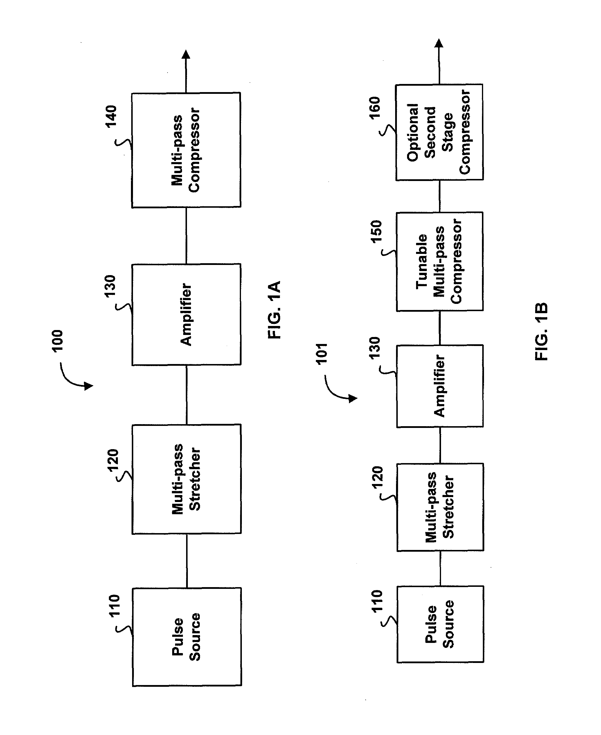
[0039]FIG. 1A is a block diagram illustrating various embodiments of a chirped pulse system generally designated 100. The chirped pulse system 100 includes a pulse source 110, an optional multi-pass stretcher 120, an amplifier 130 and an optional multi-pass compressor 140. The pulse source 110 is configured to generate a pulse having a duration, amplitude, mode, and phase profile. In various embodiments, the pulse source 110 comprises, for example, a ring laser, a laser oscillator, a chirped pulse source, a quasi-continuous wave laser, or the like. In some embodiments, the pulse source 100 generates a chirped pulse. In these embodiments, multi-pass stretcher 120 is optional. Chirped pulse system 100 includes at least one of the multi-pass stretcher 120 and the multi-pass compressor 140. For example, in some embodiments the multi-pass stretcher 120 is replaced by a single-pass stretcher of the prior art. These embodiments include the multi-pass compressor 140.

[0040]The multi-pass str...


PUM


Abstract

A chirped pulse amplification (CPA) system and method is described wherein the pulse is stretched using multiple passes through a Bragg grating or compressed using multiple passes through a Bragg grating. A switch may be used to control the number of passes through the Bragg grating, thus, tuning the compressed or the stretched pulse width. The pulse may be directed through an amplifier between the multiple passes through the Bragg grating to apply amplification to the stretched pulse multiple times. The Bragg grating may include a fiber Bragg grating, a volume Bragg grating, or a Bragg waveguide.

Description

CROSS-REFERENCE TO RELATED APPLICATIONS[0001]This application claims benefit of:[0002]U.S. Provisional Patent Application Ser. No. 60 / 761,736, filed on Jan. 23, 2006, entitled “METHOD OF DISPERSION COMPENSATION IN A CPA SYSTEM,”[0003]U.S. Provisional Patent Application Ser. No. 60 / 762,284, filed on Jan. 25, 2006, entitled “USP LASER FIBER AMPLIFIER,”[0004]U.S. Provisional Patent Application Ser. No. 60 / 763,002, filed on Jan. 26, 2006, entitled “SEED CONTROL IN ULTRA-SHORT PULSE LASER SYSTEMS,”[0005]U.S. Provisional Patent Application Ser. No. 60 / 762,791, filed on Jan. 26, 2006, entitled “AMPLIFIER CONTROL IN ULTRA-SHORT PULSE LASER SYSTEMS” and[0006]U.S. Provisional Patent Application Ser. No. 60 / 762,790, filed on Jan. 26, 2006, entitled “METHOD OF REMOTE ACCESS TO AN ULTRA-SHORT PULSE LASER SYSTEM.”[0007]This application is related to co-pending U.S. patent application entitled “Bragg Fibers in Systems for the Generation of High Peak Power Light,” Ser. No. 11 / 112,256, filed Apr. 22...

Claims


Application Information

Patent Timeline
Patent Type & Authority Patents(United States)
IPC IPC(8): G02B6/34G02B5/18
CPCH01S3/0057G02B6/2706G02B6/2931G02B6/2932H01S3/083H01S3/235
Inventor KIM, KYUNGBUMVAISSIE, LAURENTWAARTS, ROBERT G.STADLER, ANDREWCUMBO, MICHAEL J.
Owner COHERENT INC
Why Eureka
Try Eureka