Variable range ammunition cartridge for electrical discharge weapon

a technology of ammunition cartridges and electrical discharge weapons, applied in the direction of ammunition, weapons, electrical equipment, etc., can solve the problems of one dart to miss the target completely, the effectiveness between near and extended ranges is limited, and the human being can be disabled, so as to increase the effectiveness of the weapon, increase the operational limit of the current weapon, and effectively reduce the effect of the barrel pressur

Active Publication Date: 2008-11-04
VIEVU
View PDF9 Cites 44 Cited by
  • Summary
  • Abstract
  • Description
  • Claims
  • Application Information

AI Technical Summary

Benefits of technology

[0006]The present invention is directed to an improved ammunition cartridge for an electrical discharge weapon which expands the operational limits of current weapons and increases the effectiveness of the weapon at close and extended ranges. In a first embodiment the ammunition cartridge of the present invention is a variable range replacement cartridge incorporating one fixed geometry barrel and one adjustable geometry barrel. The adjustable barrel allows the user of the weapon to select between close and extended engagement ranges. The geometry of the adjustable barrel is controlled by a mechanism incorporated into the cartridge housing. The adjustable barrel is captured in the interior of the cartridge housing and, for example, is spring loaded to allow toggling between close and extended ranges. The barrel is sealed within the housing of the cartridge by a joint running perpendicular to the barrel centerline. When in the extended range setting, the adjustable barrel's porting is maximized and matched to the fixed barrel. When switched to close range the sealing joint is designed to induce turbulence, effectively decreasing barrel pressures and porting is incorporated in the sealing joint or housing to bleed pressure from the barrels or area ahead of the primer when the barrel is toggled to a specified position. This embodiment insures that optimum dart penetration is maintained.
[0007]In a second embodiment the ammunition cartridge allows the user to adjust the spread of the darts fired from the weapon to increase the effectiveness of the weapon at near, 1 to 15 feet, and extended, 15 to 30 feet, ranges. In this embodiment the ammunition cartridge includes the ability of adjusting the dart firing angle for short range or long range to allow an optimum dart spread at the target. The ammunition cartridge utilizes two fixed geometry barrels which diverge from each other by some specified angle. Canting of the ammunition cartridge within the weapon results in the top barrel having an orientation with a horizontal aim point, and the lower barrel is angled downward, causing the divergence of the darts as they are launched at the target. The ammunition cartridge adjusts the divergence of the darts by including a deflection ramp at a location where the dart first leaves the barrel.
[0008]The deflection ramp is positioned on the housing and is moved into place by means of a slider, shroud or other mechanism that can be actuated by hand while cartridge is in place in the weapon or outside the weapon. The deflection ramp makes a smooth transition from the launch angle of the barrel to the shallower or launch angle of the ramp. When the deflection ramp is retracted, the darts exit and travel along the centerline of the barrel, creating a divergence angle according to the angle between the two cartridge barrels. With the deflection ramp in the forward position, the effective exit angle of at least one of the darts is reduced, creating a shallower divergence angle, and less dart separation at longer ranges.

Problems solved by technology

Human beings can be disabled by shocks of much lower voltage, however, the higher voltage is needed to ionize air paths, so electrical currents can penetrate otherwise insulated garments worn by the human target to complete the shocking circuit through the body.
A problem with currently available ammunition cartridges is that because barrel geometries and the angle between barrels is fixed, the effectiveness between near and extended ranges is limited.
This is a problem with existing ammunition cartridges because achieving optimal dart separation at closer ranges results in too much separation at longer ranges causing one of the darts to miss the target completely.

Method used


Image

  • Variable range ammunition cartridge for electrical discharge weapon
  • Variable range ammunition cartridge for electrical discharge weapon
  • Variable range ammunition cartridge for electrical discharge weapon

Examples


Embodiment Construction

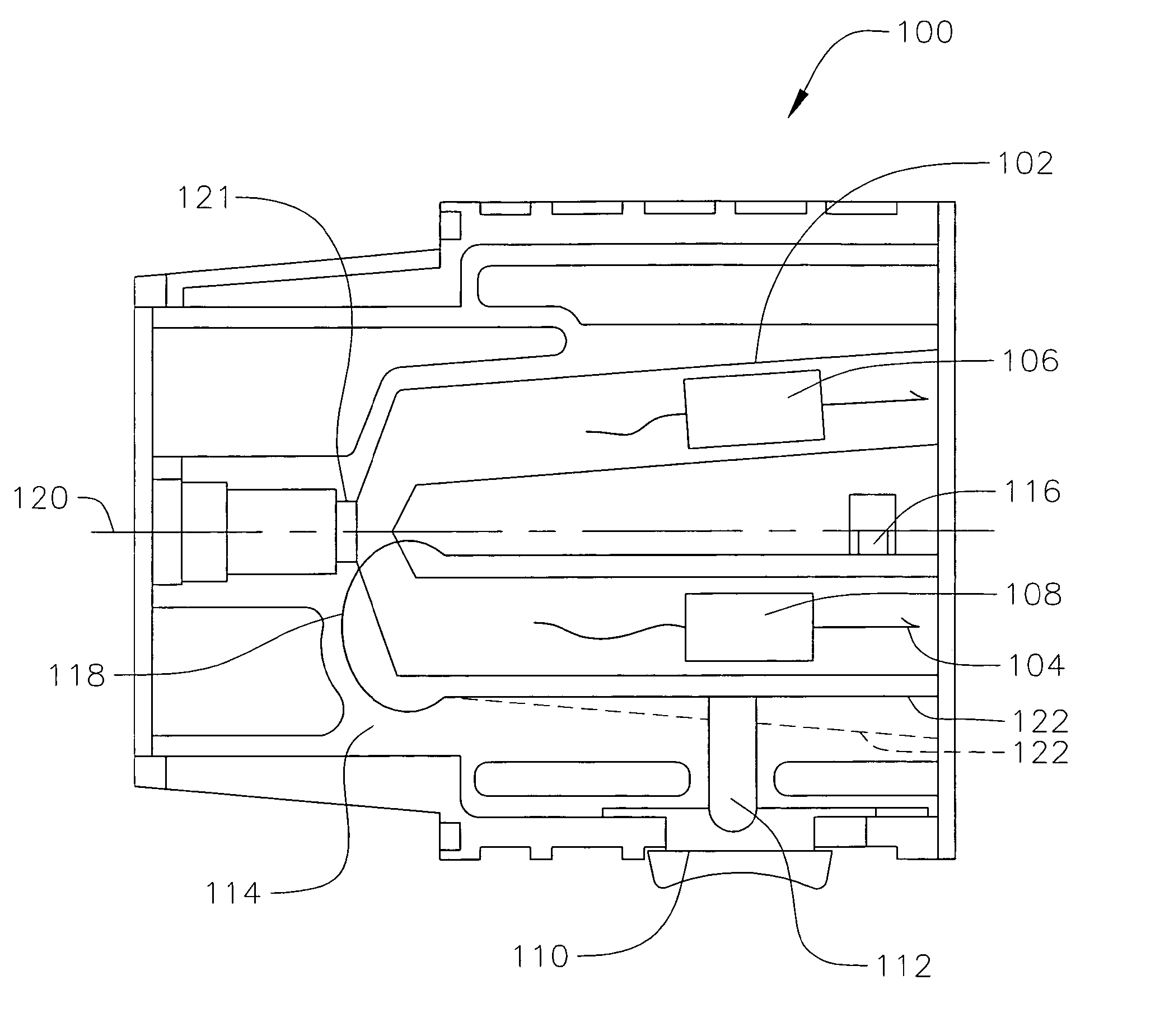
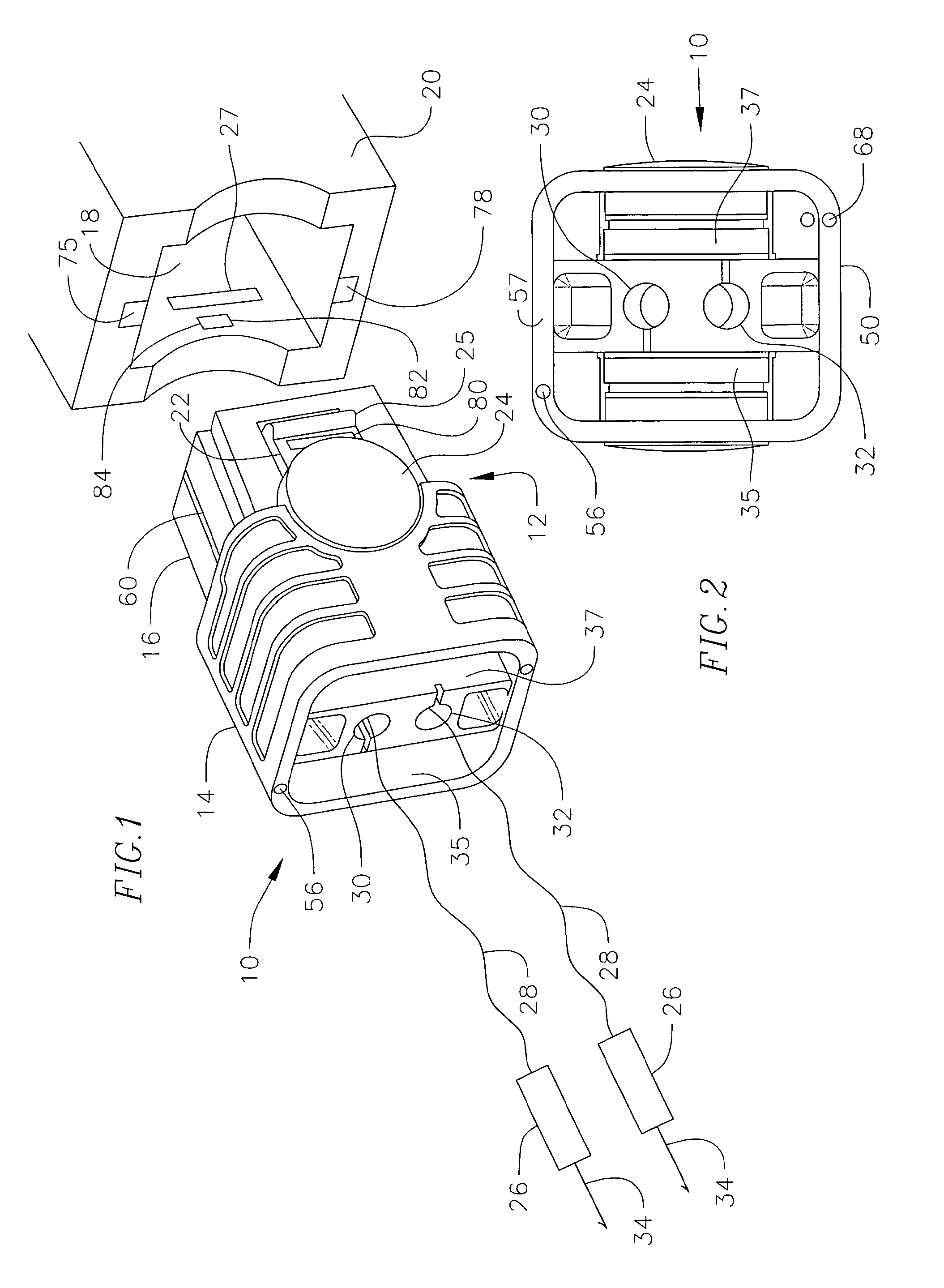
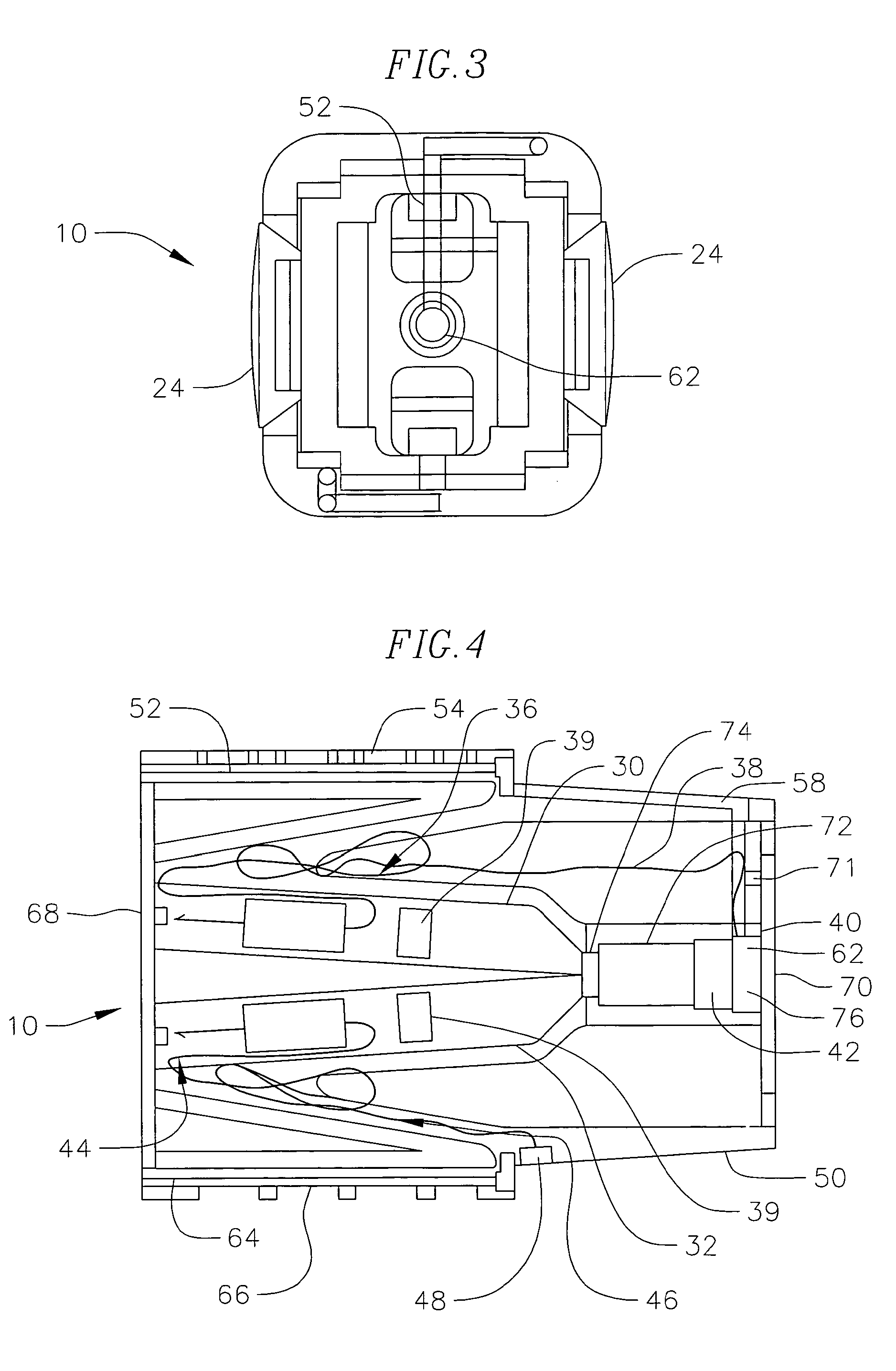
[0016]Referring to FIGS. 1 through 4, an ammunition cartridge 10 of the present invention is illustrated. The cartridge has a housing 12 formed of high impact plastic having a forward section 14, and a rear section 16. Rear section 16 is received within a cavity or receiver port 18 of an electrical discharge weapon 20. Flexible flanges 22 extend along each side of the housing, and include a boss 24 to flex the flange during insertion and removal of the cartridge from the cavity 18. The flange includes a raised stop 25 for receipt into a recess 27 in port 18 to retain the cartridge in the weapon. Dart 26 and wire assemblies 28 are positioned within dart chambers 30 and 32 contained within the housing 12. Dart chambers 30 and 32 extend into the housing at an angle so that the darts when propelled from the housing separate from one another in flight. Darts 26 each include a barbed hook 34 or other means of securing to the target such as adhesive or spiked spheres for example The wire a...


PUM


Abstract

An ammunition cartridge for an electrical discharge weapon having at least one dart positioned within a dart chamber in the housing. The cartridge has at least one adjustable barrel for selection between close and extended ranges and a joint and port for adjusting pressure in the barrel. In another form the cartridge has two fixed barrels and a retractable deflection ramp for selection between close and extended ranges.

Description

BACKGROUND OF THE INVENTION[0001]The present invention relates generally to the field of electrical immobilization weapons of the type which impart an electrical impulse to immobilize a human target by inducing involuntary muscular contractions, and more particularly, to an improved ammunition cartridge for the electrical discharge weapon which provides for a replaceable cartridge designed to expand the operational limits of the weapon by having an adjustable barrel pressure or geometry or an adjustable dart firing angle.[0002]Electrical discharge weapons, commonly sold under the trademark TASER, are weapons that connect a human target to a remote electrical power supply by means of a pair of darts and trailing conductors, so that the human target can be disabled by an electrical shock from the weapon. The typical power supply of an electrical discharge weapon produces low amperage shocks of 50 KV. Human beings can be disabled by shocks of much lower voltage, however, the higher vol...

Claims


Application Information

Patent Timeline
Patent Type & Authority Patents(United States)
IPC IPC(8): F41B15/04F41C9/00
CPCF41H13/0025F41H13/0031
Inventor KAPELES, JOHNHULTMAN, JOHN A.
Owner VIEVU
Why Eureka
Try Eureka