Hinge device with a piston/cylinder unit

a technology of piston/cylinder unit and hinge device, which is applied in the direction of vehicle body, superstructure subunit, and monocoque construction, etc., can solve the problems of high cost, complicated construction, and high cost of hinge device, and achieve the effect of increasing the stability of the hinge device, reducing the cost of construction, and simplifying construction

Inactive Publication Date: 2008-11-04
STABILUS
View PDF6 Cites 3 Cited by
  • Summary
  • Abstract
  • Description
  • Claims
  • Application Information

AI Technical Summary

Benefits of technology

[0009]The three legs, arranged on the common hinge axis, with the piston / cylinder unit arranged on them, form a premountable structural unit which is connectable as such to the fixed structural part without any appreciable outlay. Furthermore, by means of the hinge device according to an embodiment of the invention, it is possible in a simple way to move either both flaps together or only the first flap using only one piston / cylinder unit. The hinge device advantageously requires only a small installation space, and the number of structural parts required is low. This results not only in the capability of cost-effective production of the piston / cylinder unit, but also in high operating reliability and high durability. The present invention is consequently particularly suitable for use in articles exposed permanently to demanding loads and produced in large series, such as, in particular, motor vehicles. Further advantages of the hinge device of the present invention are low maintenance and low susceptibility to wear. The piston / cylinder unit advantageously comprises a pneumatic spring, in particular a pneumatic compression spring. Pneumatic springs can be produced comparatively cost-effectively in a high quality and in large quantities and have high operating reliability. A particular advantage of the invention is the low dead weight of the hinge device, this being manifested advantageously, above all, in a hinge device in a motor vehicle, since any weight reduction here not only leads to a lowering of the fuel consumption, but also helps to improve the driving behavior of the motor vehicle and reduces the production costs. A pivoting of a third leg may take place, for example, by connection to the second leg. The third leg may be connected to the second leg, for example, via a driver, in which case a freewheel stage may also be provided, as required. However, it is also conceivable, for example, to provide between the second and third leg a rigid connection which, for example in the form of a lock or a latch, is openable.
[0010]The stability of the hinge device is additionally increased and its construction further simplified when, according to an embodiment of the invention, the first leg is arranged firmly on the mount such as a fixed frame. The mount may, for example, be connected to a motor vehicle body so as to form a single structural part.
[0011]A particularly high load-bearing capacity of the hinge arrangement is achieved in that a fourth leg forms a second hinge with the third leg, the fourth leg being connectable firmly to the fixed structural part, and the first hinge and the second hinge being arranged pivotably on the common hinge axis of rotation.
[0012]The first flap may be a rear window and the second flap a tailgate of a motor vehicle.
[0013]In such a design, a damping property of the piston / cylinder unit and, moreover, its capability for moving the rear window and / or tailgate actively may advantageously be utilized.
[0014]The first flap is preferably connected via a releasable connection to the second flap such as by a lock.

Problems solved by technology

Such a hinge device is not only cost-intensive, but also has a complicated construction because of the numerous fastening elements required.
In addition to inconvenient operation, this hinge device is highly cost-intensive.

Method used


Image

  • Hinge device with a piston/cylinder unit
  • Hinge device with a piston/cylinder unit
  • Hinge device with a piston/cylinder unit

Examples


Embodiment Construction

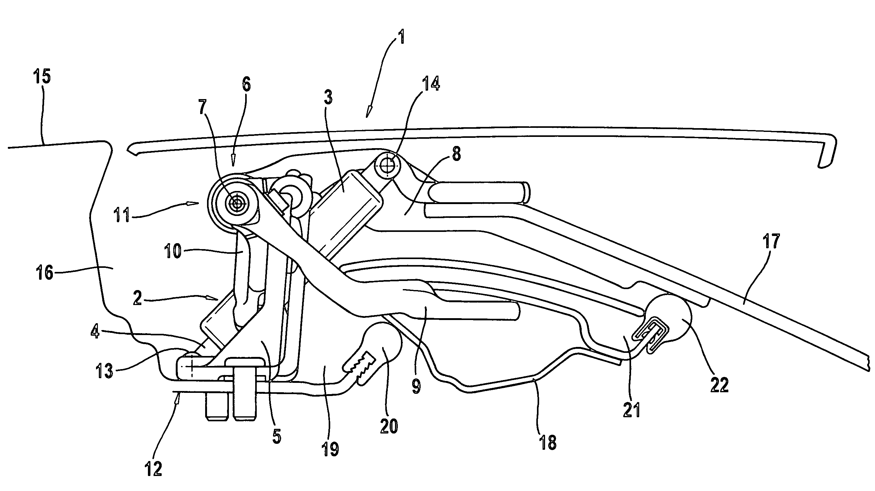
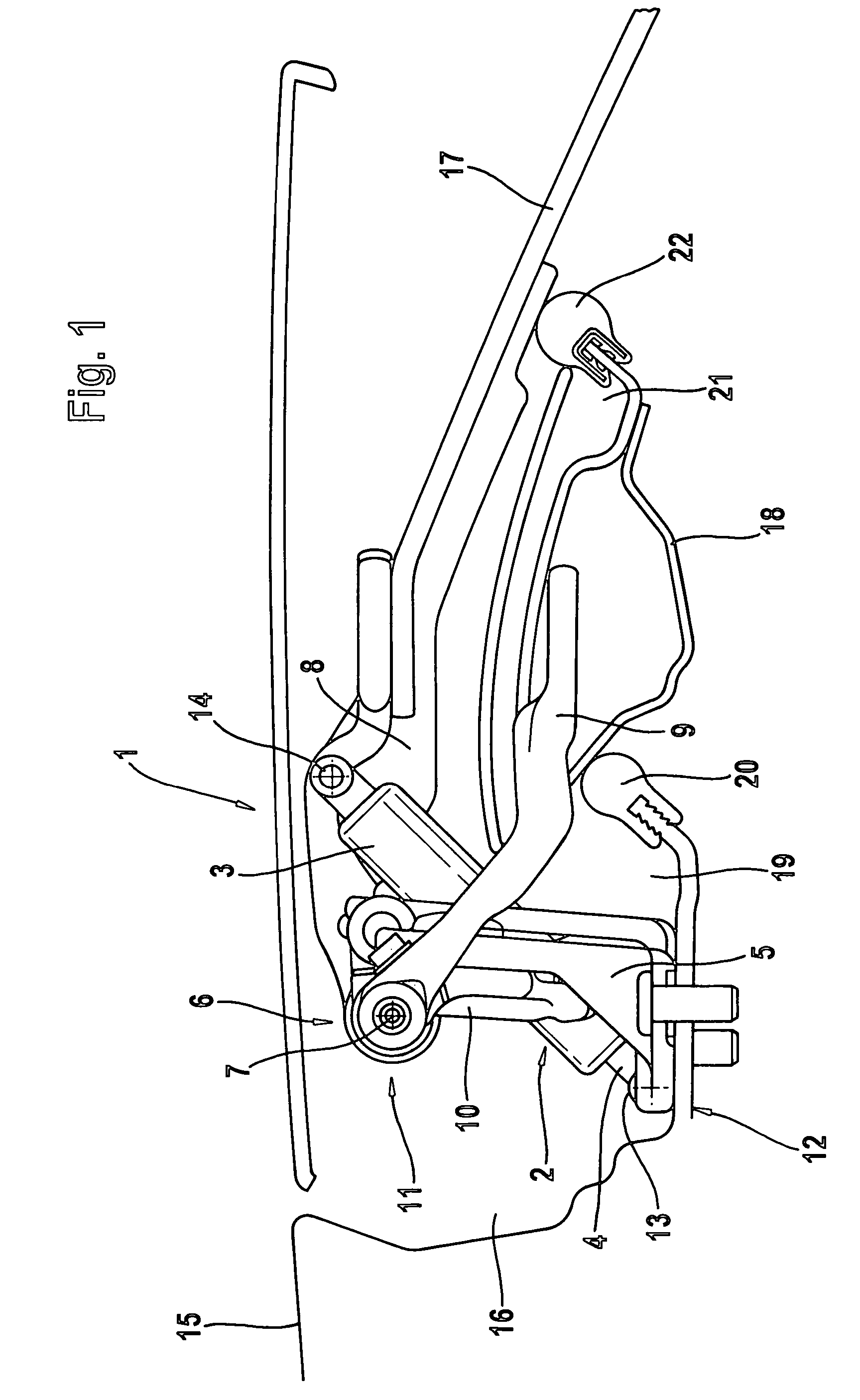
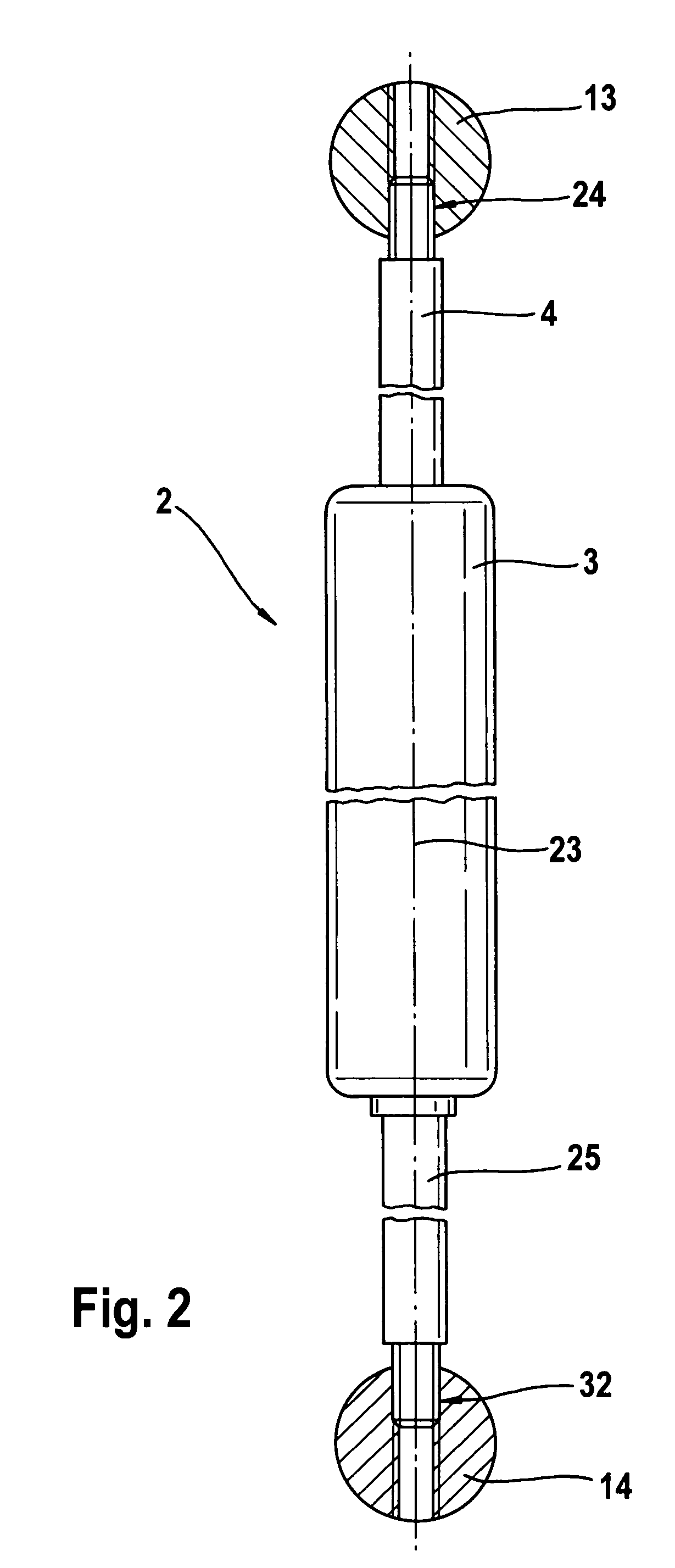
[0035]FIG. 1 shows a hinge device 1 with a piston / cylinder unit 2 which has a pressure tube 3. A piston displaceable in the pressure tube 3 is connected to a piston rod 4. In this exemplary embodiment, the piston / cylinder unit 2 is a compressed-gas pneumatic spring.

[0036]The piston / cylinder unit 2 is arranged between a first leg 5 and a second leg 8 of a first hinge 6. The second leg 8 is pivotable with respect to the first leg 5 about a common hinge axis rotation 7 of the first hinge 6. A hinge opening force, that is to say a force increasing the angle between the legs 5, 8, is applied to the legs 5, 8 by the piston / cylinder unit 2. The angle between the legs 5, 8 changes when at least one of the legs 5, 8 is released. Furthermore, a third leg 9 pivotable with respect to the first leg 5 and with respect to the second leg 8 by the piston / cylinder unit 2 is also provided.

[0037]A second hinge 11 is formed by the third leg 9 and a fourth leg 10, the hinge axis of rotation of the second...


PUM


Abstract

A hinge device for a flap of a motor vehicle includes a piston / cylinder unit arranged between a fixed structural part and a first flap which is pivotable about an axis of rotation. A second flap is likewise pivotable about the axis of rotation and can be connected releasably to the first flap. The piston / cylinder unit is arranged between a first leg, firmly connectable to the fixed structural part, and a second leg carrying the first flap, of a hinge 6. A third leg carries the second flap, wherein the first leg, the second leg, and the third leg 9 are pivotably arranged on a common hinge axis of rotation.

Description

BACKGROUND OF THE INVENTION[0001]1. Field of the Invention[0002]The present invention relates to a hinge device for a flap of a motor vehicle, the hinge device having a piston / cylinder unit, i.e., a pneumatic spring, which has a pressure tube and a piston displaceable in the pressure tube and provided with a piston rod, the piston / cylinder unit being arranged between a fixed structural part and a first flap which is pivotable about an axis of rotation and to which a second flap likewise pivotable about the axis of rotation can be connected releasably.[0003]2. Description of the Related Art[0004]A hinge device of this type is generally known from an opening arrangement for a panel of a counter. In this case, the panel is fastened to a first spar which is mounted rotatably, in each case by means of a journal, on two supporting arms forming a parallelogram. Furthermore, each of the supporting arms is mounted rotatably on a lower bearing spar by means of a further journal. Via additiona...

Claims


Application Information

Patent Timeline
Patent Type & Authority Patents(United States)
IPC IPC(8): B60J5/00
CPCE05F1/1292E05D5/043E05D5/062E05Y2900/546E05Y2600/10
Inventor CHARON, JEAN-NOELMINTGEN, ROLF
Owner STABILUS
Why Eureka
Try Eureka